Wiring diagram symbols
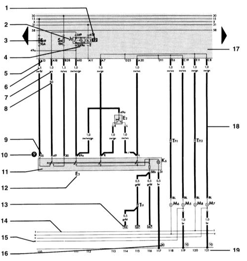 1 – Relay No. Indicates the location of the relay on the relay panel. 2 – Relay/control unit designation on the relay panel. The legend indicates the name of the component. 3 – Fuse designation. Example: fuse No. 19 (10 A) in the fuse holder. 4 – Plug connection designation on the relay panel. Example: contact 3/49a: 3 is contact 3 at position 12 of the relay panel; 49a is contact 49a on the relay/control unit. 5 – Plug connection designation on the relay panel. Example: A13 – multi-pin connector A, contact
13. 6 – Wire cross-section, mm². 7 – Wire color. Abbreviations are listed on page
289. 8 – Embossed number on white wire. Simplifies identification when there are many white wires in one harness. 9 – Terminal connection designation. C – terminal designation that can be found on the original part.
10 – Measuring point for troubleshooting. A number in a black circle refers to a figure or to an AUDI troubleshooting procedure. 11 – Hazard warning light switch designation. 12 – Component designation. The legend indicates the name of the component. 13 – Wire continuation reference. A number in a square indicates the coordinate of the continuation. 14 – Internal connection (thin line). This connection does not exist as a wire. 15 – Internal connection continuation reference. The letter indicates where the connection continues in the nearest circuit element. 16 – Ground point designation. The legend indicates the position of the ground point in the vehicle. 17 – Relay panel with fuse holder. 18 – Cable. 19 – Circuit coordinate
Test yourself
A quick Audi A3 quiz: every answer comes with an explanation and a link to the manual page.