Front Disc Brake
SPECIFICATIONS
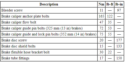
Torque Specifications
REMOVAL AND INSTALLATION
Brake Pads - 325 mm (13 in) Brakes
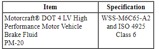
Material
Removal
WARNING: Before beginning any service procedure in this section, refer to Safety Warnings in Section 100-00. Failure to follow this instruction may result in serious personal injury.
NOTICE: Do not spill brake fluid on painted or plastic surfaces or damage to the surface may occur. If brake fluid is spilled onto a painted or plastic surface, immediately wash the surface with water.
NOTICE: Do not allow grease, oil, brake fluid or other contaminants to contact the pad lining material, or damage to components may occur. Do not install contaminated pads.
NOTE: Removal steps in this procedure may contain installation details.
- NOTE: The master cylinder reservoir should be half full to avoid overflow when the brake caliper pistons are retracted.
Visual check. Extract the fluid with a syringe.
- Remove the wheel and tire. For additional information, REFER to Section 204-04.
- NOTICE: Do not allow the brake caliper to hang from the brake flexible hose and or damage to the hose may occur.
NOTICE: Make sure the brake caliper guide pin bolts are clean and free of debris or a binding condition may occur.
NOTICE: Do not allow the brake flexible hose to get twisted when the caliper is repositioned on the brake caliper anchor plate or damage to the hose may occur.
Relocate and support the component.- To install, tighten to 72 N·m.
- NOTE: During installation, the coil in the center of the wire spreader spring must lie against the anchor plate and must not be in the raised position. If the coil in the center of the wire spreader spring does not rest against the caliper anchor plate, the spring is installed incorrectly and must be repositioned.
- NOTICE: Make sure the caliper pin boots are correctly seated to prevent corrosion to the guide pins.
Visual check.
Installation
- NOTE: If installing new brake pads, make sure to install all new hardware and lubricant supplied with the brake pad kit. Refer to the brake pad instruction sheet when applying lubricant.
To install, reverse the removal procedure.
- Visual check.
Brake Pads - 352 mm (14 in) Brakes
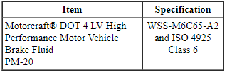
Material
Removal
WARNING: Before beginning any service procedure in this section, refer to Safety Warnings in Section 100-00. Failure to follow this instruction may result in serious personal injury.
NOTICE: Do not spill brake fluid on painted or plastic surfaces or damage to the surface may occur. If brake fluid is spilled onto a painted or plastic surface, immediately wash the surface with water.
NOTICE: Do not allow grease, oil, brake fluid or other contaminants to contact the pad lining material, or damage to components may occur. Do not install contaminated pads.
NOTE: Removal steps in this procedure may contain installation details.
- NOTE: The master cylinder reservoir should be half full to avoid overflow when the brake caliper pistons are retracted.
Visual check. Extract the fluid with a syringe.
- Remove the wheel and tire. For additional information, REFER to Section 204-04.
- NOTICE: Do not allow the brake caliper to hang from the brake flexible hose and or damage to the hose may occur.
NOTICE: Make sure the brake caliper guide pin bolts are clean and free of debris or a binding condition may occur.
NOTICE: Do not allow the brake flexible hose to get twisted when the caliper is repositioned on the brake caliper anchor plate or damage to the hose may occur.
Relocate and support the component.- To install, tighten to 75 N·m.
- NOTICE: Make sure the caliper pin boots are correctly seated to prevent corrosion to the guide pins.
Visual check.
Installation
- NOTE: If installing new brake pads, make sure to install all new hardware and lubricant supplied with the brake pad kit. Refer to the brake pad instruction sheet when applying lubricant.
To install, reverse the removal procedure.
- Visual check.
Brake Caliper
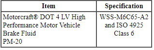
Material
Removal
WARNING: Before beginning any service procedure in this section, refer to Safety Warnings in Section 100-00. Failure to follow this instruction may result in serious personal injury.
NOTICE: Do not spill brake fluid on painted or plastic surfaces or damage to the surface may occur. If brake fluid is spilled onto a painted or plastic surface, immediately wash the surface with water.
NOTICE: Do not allow grease, oil, brake fluid or other contaminants to contact the pad lining material, or damage to components may occur. Do not install contaminated pads.
NOTE: Removal steps in this procedure may contain installation details.
NOTE: 352 mm (14 in) brakes shown, 325 mm (13 in) brakes similar.
- Discard the specified component. Follow local disposal regulations.
- To install, tighten to 47 N·m.
- NOTICE: Make sure the brake caliper guide pin bolts are clean and free of debris or a binding condition may occur.
NOTICE: Make sure the caliper pin boots are correctly seated to prevent corrosion to the guide pins.
- 325 mm (13 in) brakes: To install, tighten to 72 N·m.
- 352 mm (14 in) brakes: To Install, tighten to 75 N·m.
Installation
- To install, reverse the removal procedure.
- Lubricate the brake caliper flow bolt threads and new washers with clean specified brake fluid before installing the brake caliper flow bolt into the brake caliper.
- Bleed the brake caliper. For additional information, REFER to Section 206-00 for Component Bleeding.
Brake Caliper Anchor Plate
Removal
WARNING: Before beginning any service procedure in this section, refer to Safety Warnings in Section 100-00. Failure to follow this instruction may result in serious personal injury.
NOTE: Removal steps in this procedure may contain installation details.
All vehicles
- Remove the brake pads. For additional information, refer to Brake Pads - 352 mm (14 in) Brakes or Brake Pads - 325 mm (13 in) Brakes in this section.
Vehicles with 352 mm (14 in) brakes
- Relocate and support the component.
- To install, tighten to 75 N·m.
All vehicles
- NOTE: 352 mm (14 in) brakes shown, 325 mm (13 in) brakes similar.
Discard the specified component. Follow local disposal regulations.
- To install, tighten to 165 N·m.
Installation
- To install, reverse the removal procedure.
Brake Disc
Material

Removal
WARNING: Before beginning any service procedure in this section, refer to Safety Warnings in Section 100-00. Failure to follow this instruction may result in serious personal injury.
NOTE: Removal steps in this procedure may contain installation details.
NOTE: 352 mm (14 in) brakes shown, 325 mm (13 in) brakes similar.
- Remove the wheel and tire. For additional information, REFER to Section 204-04.
- NOTICE: Do not allow the brake caliper to hang from the brake flexible hose or damage to the hose may occur.
Relocate and support the component. Discard the specified component. Follow local disposal regulations.
- To install, tighten the new bolts to 165 N·m.
- NOTE: If necessary, thread a M10 bolt into the brake disc removal hole and tighten to press the disc off the hub.
Discard the specified component. Follow local disposal regulations.
- To install, tighten the new screw to 20 N·m.
Installation
- Visual check. Wire brush. Clean the specified component with the specified material.
- To install, reverse the removal procedure.
Brake Disc Shield
Removal
WARNING: Before beginning any service procedure in this section, refer to Safety Warnings in Section 100-00. Failure to follow this instruction may result in serious personal injury.
NOTE: Removal steps in this procedure may contain installation details.
NOTE: 352 mm (14 in) brakes shown, 325 mm (13 in) brakes similar.
- Remove the brake disc. For additional information, refer to Brake Disc in this section.
- To install, tighten to 15 N·m.
Installation
- To install, reverse the removal procedure.
Brake Flexible Hose
Material
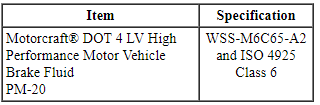
Removal
WARNING: Before beginning any service procedure in this section, refer to Safety Warnings in Section 100-00. Failure to follow this instruction may result in serious personal injury.
NOTICE: Do not spill brake fluid on painted or plastic surfaces or damage to the surface may occur. If brake fluid is spilled onto a painted or plastic surface, immediately wash the surface with water.
NOTICE: Do not allow grease, oil, brake fluid or other contaminants to contact the pad lining material, or damage to components may occur. Do not install contaminated pads.
NOTE: Removal steps in this procedure may contain installation details.
NOTE:
- With the vehicle in NEUTRAL, position it on a hoist. For additional information, REFER to Section 100-02.
- NOTICE: Make sure to protect the brake pads from contamination from the brake fluid during the brake flexible hose installation and the brake caliper bleeding.
- To install, tighten the brake tube fiting to 17 N·m.
- To install, tighten the brake flexible hose bracket bolt to 30 N·m.
- Discard the specified component. Follow local disposal regulations.
- To install, tighten to 47 N·m.
Installation
- To install, reverse the removal procedure.
- Lubricate the brake caliper flow bolt threads and new washers with clean brake fluid before installing the brake caliper flow bolt into the brake caliper.
- Bleed the brake caliper. For additional information, REFER to Section 206-00 for Component Bleeding.
Test yourself
A quick Ford Taurus quiz: every answer comes with an explanation and a link to the manual page.