Accessories
Dashboard/Steering Hanger Beam Disassembly and Reassembly (Without Navigation)

SRS components are located in this area. Review the SRS component locations and the precautions and procedures before doing repairs or service.
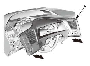
- Dashboard Subdisplay Visor
 |
|
1. |
Remove the dashboard subdisplay visor (A). |
|
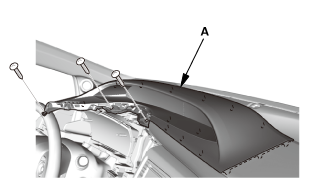
- Dashboard Meter Visor
 |
|
1. |
Remove the dashboard meter visor (A). |
|
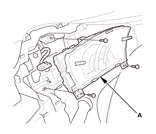
- Gauge Control Module - Tach
 |
|
1. |
Remove the gauge control module (tach) (A). |
|
2. |
Disconnect the connector. |
|
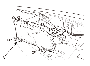
- Information Display Unit
 |
|
1. |
Remove the information display unit (A). |
|
2. |
Disconnect the connectors. |
|
- Multi-Information Display Unit
|
|
1. |
Remove the multi-information display unit (A). |
|
2. |
Disconnect the connectors. |
|
- Gauge Control Module - Speedo
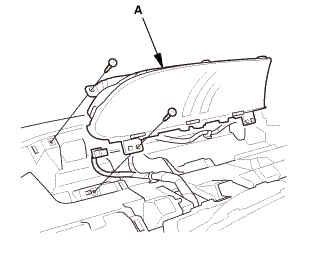 |
|
1. |
Remove the gauge control module (speedo) (A). |
|
2. |
Disconnect the connector. |
|
- Center Lower Panel
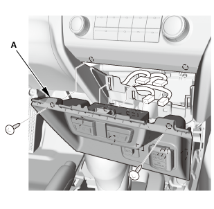 |
|
1. |
Remove the center lower panel (A). |
|
NOTE: Take care not to scratch the center console panel or the related parts. |
|
- Audio Unit Assembly
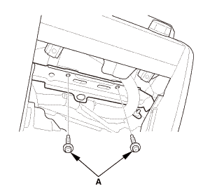 |
NOTE:
|
 |
Lay a workshop towel under the parts when working on them to protect the face panel from scratches or other damage. |
|
|
|
Do not work in a dusty or dirty place. |
|
|
|
Discharge static electricity from your body before and during the work. |
|
|
|
Do not touch the circuit board(s) with your bare hands. |
|
|
|
Do not work with dirty hands. |
|
|
|
Do not touch the terminal connector of the flat plate cable with your bare hands (If you have touched it, wipe it off thoroughly.). |
|
|
|
Eject the CD before disconnecting the audio unit to prevent damaging the CD player’s load mechanism. |
|
|
|
If you are replacing the audio unit, write down the audio presets (if possible), and enter them into the new audio unit. |
|
|
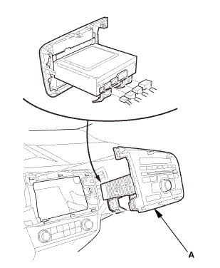 |
|
2. |
Disconnect the connectors, then pull out the audio unit (A). |
|
- Audio Unit Assembly (With display audio)
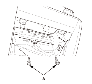 |
NOTE:
|
|
Lay a workshop towel under the parts when working on them to protect the face panel from scratches or other damage. |
|
|
|
Do not work in a dusty or dirty place. |
|
|
|
Discharge static electricity from your body before and during the work. |
|
|
|
Do not touch the circuit board(s) with your bare hands. |
|
|
|
Do not work with dirty hands. |
|
|
|
Do not touch the terminal connector of the flat plate cable with your bare hands (If you have touched it, wipe it off thoroughly.). |
|
|
|
Eject the CD before disconnecting the audio unit to prevent damaging the CD player’s load mechanism. |
|
|
|
If you are replacing the audio unit, write down the audio presets (if possible), and enter them into the new audio unit. |
|
|
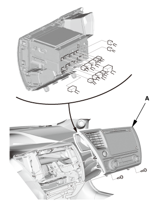 |
|
2. |
Disconnect the connectors, then pull out the audio unit assembly (A). |
|
- Front Passenger's Airbag Assembly
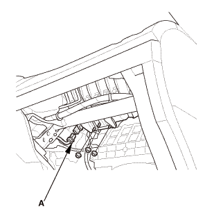 |
|
1. |
Disconnect the front passenger's airbag inflator connector (A) on the dashboard wire harness. |
|
2. |
Remove the mounting nuts. |
|
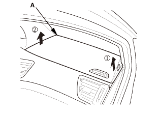
 |
|
3. |
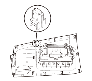
Gently remove the front passenger's airbag and lid assembly (A). |
|
NOTE: The airbag lid has clips on each side where it attaches to the dashboard. |
|
- Center Joint Duct
 |
|
1. |
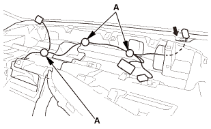
Detach the harness clips (A). |
|
 |
|
2. |
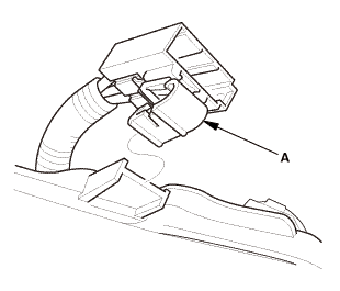
Detach the connector clip (A) from side edge of the dashboard. |
|
 |
|
3. |
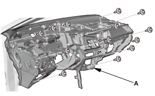
Remove the dashboard (A). |
|
 |
|
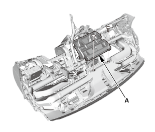
4. |
Remove the center joint duct (A). |
|
- Steering Hanger Beam
 |
|
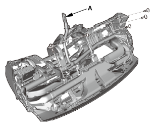
1. |
Remove the steering hanger beam (A). |
|

SRS components are located in this area. Review the SRS component locations and the precautions and procedures before doing repairs or service.
- Steering Hanger Beam
 mm22u....z1
|
|
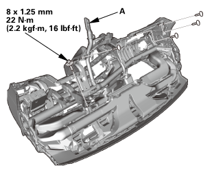
1. |
Install the steering hanger beam (A). |
|
- Center Joint Duct
|
|
1. |
Install the center joint duct (A). |
|
 mmto
|
|
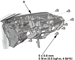
2. |
Install the dashboard (A). |
|
|
|
3. |
Install the connector clip (A) to side edge of the dashboard. |
|
|
|
4. |
Install the harness clips (A). |
|
- Front Passenger's Airbag Assembly
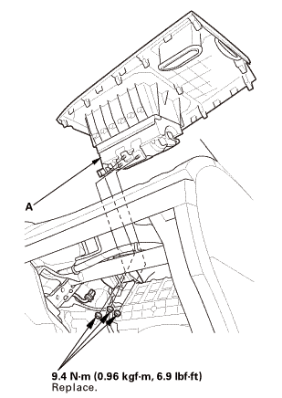 |
|
1. |
Place the front passenger's airbag and lid as an assembly (A) into the dashboard. |
|
2. |
Tighten the new mounting nuts. |
|
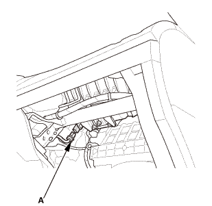 |
|
3. |
Connect the front passenger's airbag inflator connector (A) on the dashboard wire harness. |
|
- Audio Unit Assembly (With display audio)
|
|
1. |
Connect the connectors, then install the audio unit assembly (A). |
|
NOTE: Make sure all the connectors and the antenna lead are securely connected. |
|
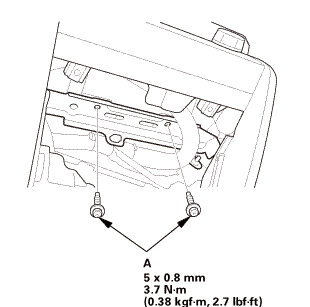 |
|
2. |
Install the bolts (A). |
|
- Audio Unit Assembly
|
|
1. |
Connect the connectors, then install the audio unit (A). |
|
NOTE: Make sure all the connectors and the antenna lead are securely connected. |
|
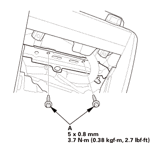 n.amm2.72.7
|
|
2. |
Install the bolts (A). |
|
- Center Lower Panel
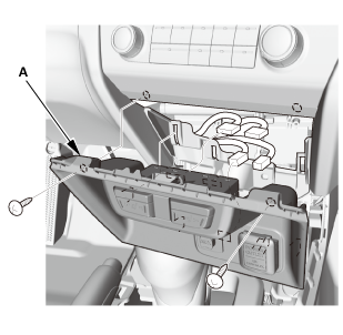 |
|
1. |
Install the center lower panel (A). |
|
NOTE: Take care not to scratch the center console panel or the related parts. |
|
- Gauge Control Module - Speedo
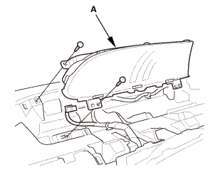 |
|
1. |
Connect the connector. |
|
2. |
Install the gauge control module (speedo) (A). |
|
- Multi-Information Display Unit
|
|
1. |
Connect the connectors. |
|
2. |
Install the multi-information display unit (A). |
|
- Information Display Unit
|
|
1. |
Connect the connectors. |
|
2. |
Install the information display unit (A). |
|
- Gauge Control Module - Tach
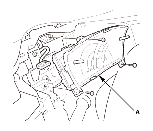 |
|
1. |
Connect the connector. |
|
2. |
Install the new gauge control module (tach) (A). |
|
- Dashboard Meter Visor
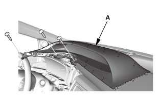 |
|
1. |
Install the dashboard meter visor (A). |
|
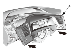
- Dashboard Subdisplay Visor
 |
|
1. |
Install the dashboard subdisplay visor (A). |
|
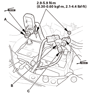
- Battery Terminal (SRS) - Reconnection
 (o.2ao.sam.
|
NOTE: If the battery performs abnormally, test the battery.
|
1. |
Clean the battery terminals. |
|
2. |
Connect the positive cable (A) to the battery. |
|
NOTE: Always connect the positive side first. |
|
3. |
Connect the negative cable and the battery sensor (B) to the battery. |
|
NOTE: To protect the battery sensor connector (C) from damage, do not hold it when installing the negative terminal. |
|
4. |
Apply multipurpose grease to the terminals to prevent corrosion. |
|
?
Test yourself
A quick Honda Civic quiz: every answer comes with an explanation and a link to the manual page.
Was this page helpful?