Repair procedures
Removal
Disconnect the negative (-) battery terminal.
Remove the steering wheel.
(Refer to Steering System - "Steering Wheel")
Remove the steering column upper and lower shrouds after loosening the screws.
(Refer to Body - "Steering Column Shroud Panal")
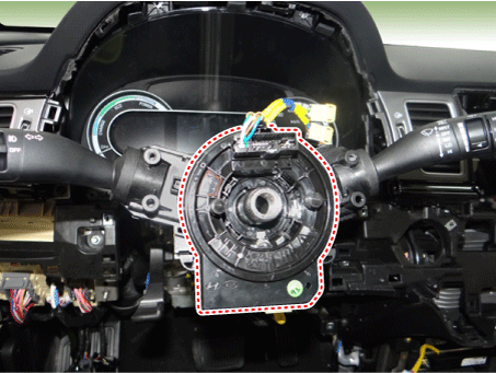
Remove the clock spring.
(Refer to Restraint - "Driver Airbag (DAB) Module and Clock Spring")
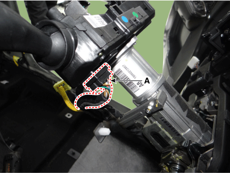
Disconnect the multifunction switch connector (A).
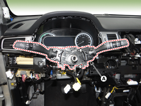
Remove the multifunction switch assembly (A) after loosening the screws.
Installation
Install the multifunction switch.
Install the clock spring.
Install the steering column upper and lower shrouds.
Install the steering wheel.
Connect the negative (-) battery terminal.
Inspection
Multifunction Switch Inspection
Check for continuity between the terminals in each switch position as shown below.
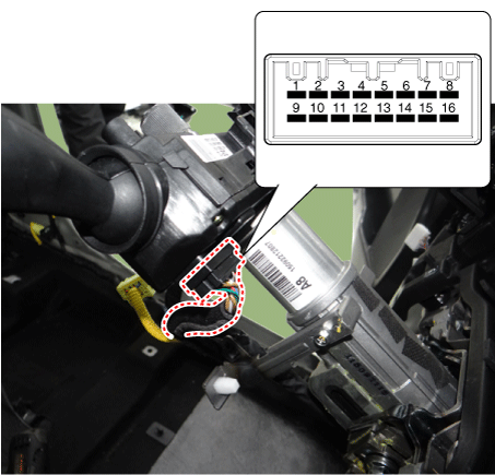
[Left Handle Drive]
Switch Switch position Switch terminal Resistance (?, ±3.5%) Front wiper switch MIST 1-9 330 OFF ? Intermittent (AUTO) 800 LOW 1,800 HIGH 5,700 Rear wiper switch OFF 9-16 ? LOW 910 HIGH 2,910 Wiper intermittent volume Volume 1 7-9 330 Volume 2 690 Volume 3 1,310 Volume 4 2,610 Volume 5 7,310 Fog lamp switch OFF 9-10 ? Front fog lamp 910 Rear fog lamp 2,910 Turn signal switch OFF 9-12 ? Left 910 Right 2,910 Dimmer & Passing switch OFF 9-13 ? Passing 910 Dimmer 2,910 Light switgh OFF 9-14 ? AUTO / DRL 680 Tail lamp 1,680 Low beam 5,580
[Right Handle Drive]
Switch Switch position Switch terminal Resistance (?, ±3.5%) Front Wiper switch MIST 3-16 330 OFF ? Intermittent (AUTO) 800 LOW 1,800 HIGH 5,700 Rear wiper switch OFF 9-16 ? LOW 910 HIGH 2,910 Wiper intermittent volume Volume 1 2-16 330 Volume 2 690 Volume 3 1,310 Volume 4 2,610 Volume 5 7,310 Fog lamp switch OFF 14-16 ? Front fog lamp 910 Rear fog lamp 2,910 Turn signal switch OFF 13-16 ? Left 910 Right 2,910 Dimmer & Passing switch OFF 12-16 ? Passing 910 Dimmer 2,910 Light switgh OFF 11-16 ? AUTO / DRL 680 Tail lamp 1,680 Low beam 5,580
Inspection (With KDS/GDS)
In the body electrical system, failure can be quickly diagnosed by using the vehicle diagnostic system (KDS/GDS).
The diagnostic system(KDS/GDS) provides the following information.
Self diagnosis : Checking failure and code number (DTC)
Current data : Checking the system input/output data state
Actuation test : Checking the system operation condition
Additional function : Controlling other features including system option setting and zero point adjustment
Select the 'Car model' and the 'Body Control Module (BCM)' to be checked in order to check the vehicle with the tester.
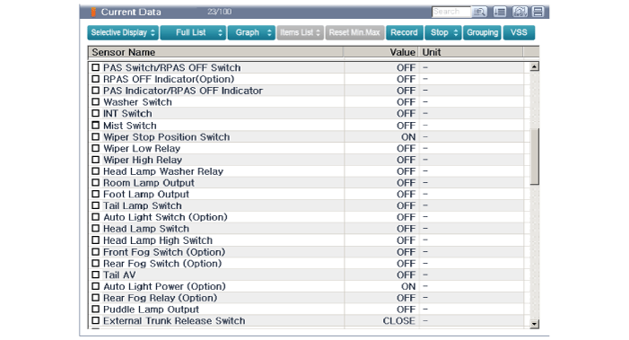
Select the 'Current Data' menu to search the current state of the input/output data.