Repair procedures
Self Diagnosis
Self-diagnosis process.

Fault code display
Continuance operation : DTC code.

Continuance operation : DTC code.

STEP operation.
A. Same with continuance operation for normal or one fault code
B. DTC code.
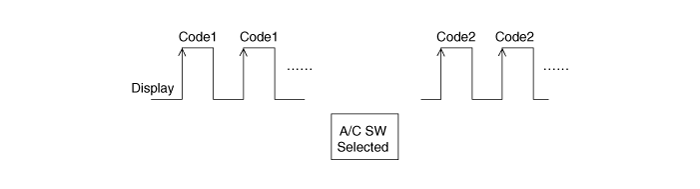
If fault codes are displayed during the check, inspect malfunction causes by referring to fault codes.
Display Fail description 0 Normal 11 In-car sensor open 12 In-car sensor short 13 Ambient sensor open 14 Ambient sensor short 17 Evaporator sensor open 18 Evaporator sensor short 19 Temp door potentiometer open/short- Drive 20 Temp door potentiometer fault- Drive 21 Mode door potentiometer open/short - Driver 22 Mode door potentiometer fault - Driver 23 Auto Defog Sensor Open 24 Auto Defog Sensor Short 25 Intake door potentiometer open 26 Intake door potentiometer short 32 Temp door potentiometer open/short - Passenger 33 Temp door potentiometer fault - Passenger 43 Defog door potentiometer open/short 44 Defog door potentiometer fault 45 APT CAN signal fault 48 Vehicle speed CAN signal fault 49 Engine coolant temp CAN signal fault 50 Cluster Ionizer Fault 51 Duct sensor vent open - Drive 52 Duct sensor vent shot - Drive 53 Duct sensor floor open - Drive 54 Duct sensor floor shot - Drive 55 Mode door potentiometer open/short- Passenger 56 Mode door potentiometer fault- Passenger 60 COMP CAN signal fault 61 COMP operation state ERROR received 62 Low_Voltage 63 High_Voltage 64 Cold protection 65 Overheat protection 67 Overcurrent protection 68 Abnormal current sensor 69 Restart failure 70 Overload 71 A/C operating permission is not received 72 A/C allowable power is not received 73 A/C allowable power is the inoperative range of E-COMP 74 APT high pressure 75 APT low pressure 76 Ordering A/C operation to stop (from EMS) 77 Airbag Deployment (Ordering E-COMP operation to stop) 78 Compressor Interlock Circuit OPEN 85 Blower Motor fault Fail safe
NO Item Fault Fail Safe 1 In-car sensor Open or Short Control with the value of 25 °C 2 Ambient sensor Open or Short Control with the value of 20 °C 3 Evaporator sensor Open or Short Control with the value of -2°C (28.4°F) 4 Temperature control actuator Open or Short If temperature setting 17 °C - 24 °C, fix at maximum cooling position.
If temperature setting 25 °C - 32 °C, fix at maximum heating position.5 Mode control actuator Open or Short Fix vent position, while selecting vent mode.
Fix defrost position, while selecting all except vent mode.6 Intake control actuator Open or Short Fix fresh position, while selecting fresh mode.
Fix recirculation position, while selecting recirculation mode.7 Vehicle speed NO reception A/C OFF (Control with the value of 0 km/h) 8 Engine coolant temperature NO reception Control with the value of 90 °C 9 APT NO reception COMP operation stop (RPM=0) 10 COMP Inverter Inverter WAIT/SLEEP Mode entry COMP operation stop (RPM=0) 11 A/Con operating permission FFh or NO reception COMP operation stop (RPM=0) 12 A/C Compressor permission power FFh or NO reception COMP operation stop (RPM=0) 13 CF_Hcu_PTOperMod FFh or NO reception EV Mode substitute control 14 Defogging door potentiometer Open or Short In the VENT, Bi-Level mode, DEF Door Potentiometer is fixed in CLOSE position.
In the mode other VENT, Bi-Level mode, DEF Door Potentiometer is fixed in OPEN position.15 Passenger mode door potentiometer Open or Short In the VENT mode, PS Mode Door Potentiometer is fixed in VENT position.
In the mode other than VENT, PS Mode Door Potentiometer is fixed in DEF position.16 Duct sensor_Vent [LH] Open or Short In case of the Duct sensor failure, replace the Duct sensor with Temp Door mapping. 17 Duct sensor_Floor [LH] Open or Short In case of the Duct sensor failure, replace the Duct sensor with Temp Door mapping.
Replacement
Disconnect the negative (-) battery terminal.
Using a screwdriver or remover, remove the front console garnish (A).
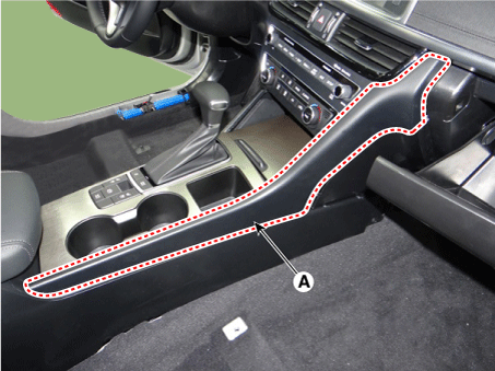
Using a remover, remove the crash pad side cover [RH] (A).

Loosen the screw and remove the crash pad plate [RH] (A).
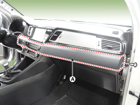
Remove the engine start button connector (A).
Remove the center fascia panel (A).
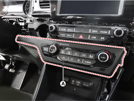
Loosen the screw and remove the heater and air conditioner control unit (A).

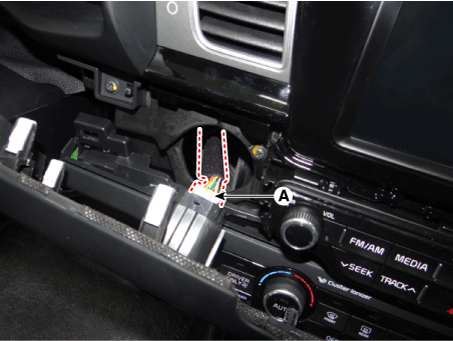
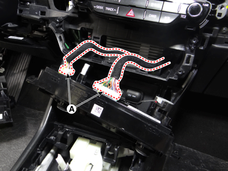
Remove the heater and the air conditioning control unit connector (A).
Install in the reverse order of removal.