Kia Sorento XM 2011-2023 Repair Manual
Smart Key Diagnostic Inspection
In this manual: Kia Sorento XM 2011-2023 Repair Manual
43steps
~258min
4/5difficulty
Done 0 of 43
Self-Diagnosis Using GDS: Smart key system defects can be quickly diagnosed using GDS. GDS operates the actuator quickly to monitor the input/output value and self-diagnosis. The following three functions will be a major concern in the SMART KEY system.
Actuator List
- SMART KEY Device Input Problem.
- SMART KEY Unit Problem.
- SMART KEY Device Output Problem.
- SMART KEY Unit Input Problem: Switch Diagnosis
- SMART KEY Unit Problem: Communication Diagnosis
- SMART KEY Unit Output Problem: Antenna and Switch Diagnosis
- Connect the GDS cable to the data link connector in the driver side lower panel, then turn on the GDS power.
- Select the vehicle model, then select the SMART KEY system.

- Select "SMART KEY Device".
- After turning the IG on, select "Current Data".
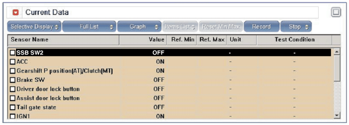
- You can check the position of each switch on the scan tool after connecting it, using the "Current Data" function.
Display Description FL Switch ON: The driver's door handle button is on. FR Switch ON: The auxiliary door handle button is on. Trunk Opener Switch ON: External line button is on. Gear Position P ON: The shift lever is in the P position. IGN 1 ON: The IGN switch is in the IG position. ACC ON: The IGN switch is in the ACC position. External Buzzer ON: Buzzer is on. - Communication diagnosis checks that all related components operate normally.
- Connect the GDS cable to the data link connector in the driver's side lower panel.
- After turning the ignition switch ON, select "DTC".
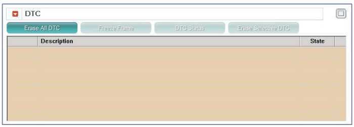
- Connect the GDS cable to the data link connector in the driver's side lower panel.
- With the ignition switched ON, select "ACTUATOR TEST".
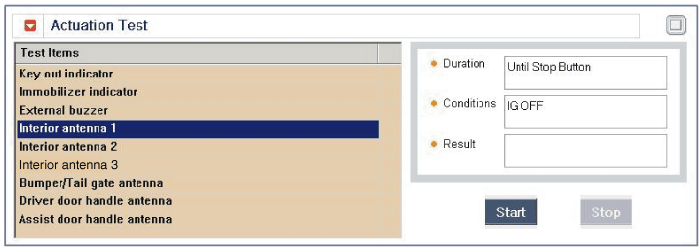
- Place the smart key near the corresponding antenna and operate it using GDS.
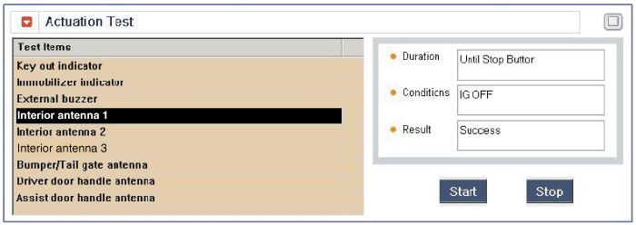
- If the smart key LED blinks, the smart key is normal.
- If the Smart Key LED does not blink, check the voltage of the Smart Key battery.
- Antenna Activation
A. INTERIOR Antenna 1 B. INTERIOR Antenna 2 C. INTERIOR Antenna 3 D. BUMPER Antenna E. DRV_DR Antenna F. AST_DR Antenna - Connect the GDS cable to the data link connector in the driver's side lower panel.
- Select "Antenna Status Check".
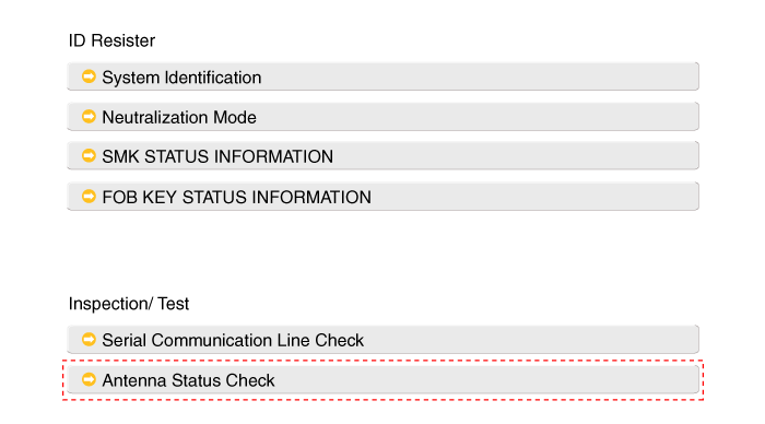
- After turning the IG switch ON, select "Antenna Status Check".
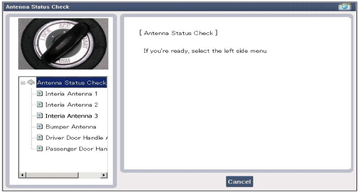
- Place the smart key near the corresponding antenna and operate it using GDS.
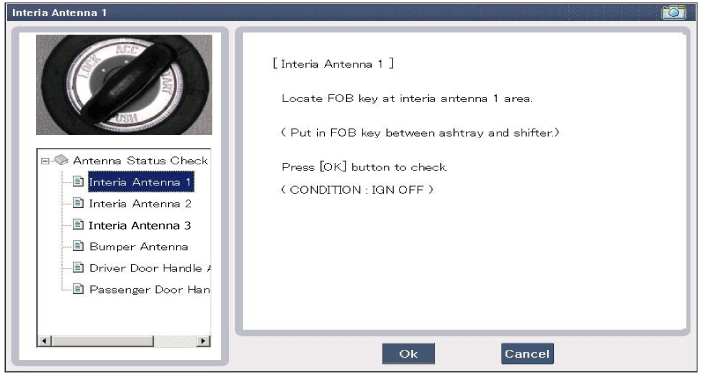

- If the Smart Key operates normally, the corresponding antenna, Smart Key (transmission, reception) and external receiver are normal.
- Antenna Status
A. INTERIOR Antenna 1 B. INTERIOR Antenna 2 C. INTERIOR Antenna 3 D. BUMPER Antenna E. DRV_DR Antenna F. AST_DR Antenna - Connect the GDS cable to the data link connector in the driver's side lower panel.
- Select "Serial Link Check".
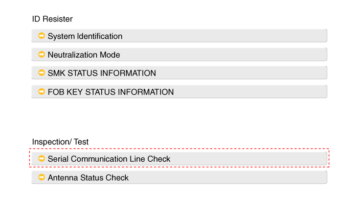
- With the ignition switched ON, select "Receiver Communication Line Check".
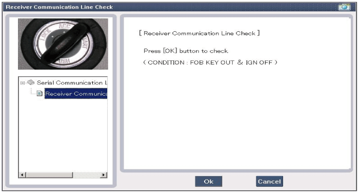
- Check the serial communication line using the GDS.
- If the smart key operates normally, communication of the smart key unit, external receiver and ESCL is normal.
- If the smart key does not operate normally, check the following items.
A. Open circuit or no response from the external receiver communication line. B. Short of the external receiver communication line to ground. C. Open circuit in ESCL or no response. D. Short to ground in ESCL. - Place the smart key in the following blind zone and check IG ON.
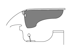
- If the ignition is on, the antenna operates normally.
- Check the ignition mode of the internal antenna.
- Place the smart key in the following blind zone and activate the antenna. Make sure the smart key LED blinks.
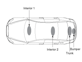
- If the smart key LED does not blink, check the antenna in the blind zone.
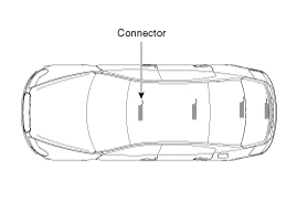
- Connect the GDS cable to the data link connector in the driver's side lower panel.
- After turning the ignition ON, select "KEY FOB STATUS INFO".
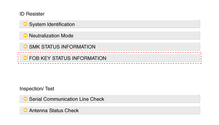
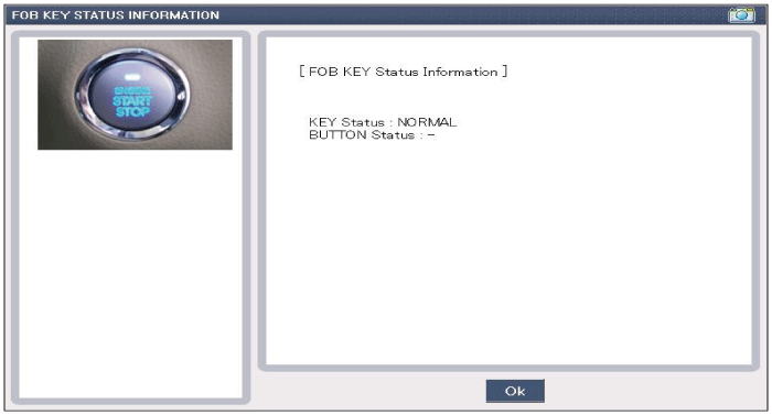
- Connect the GDS cable to the data link connector in the driver's side lower panel.
- After turning the ignition switch ON, select "SMK STATUS INFO".
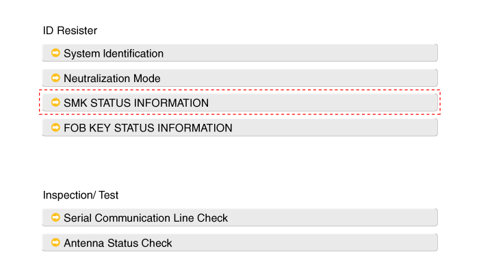
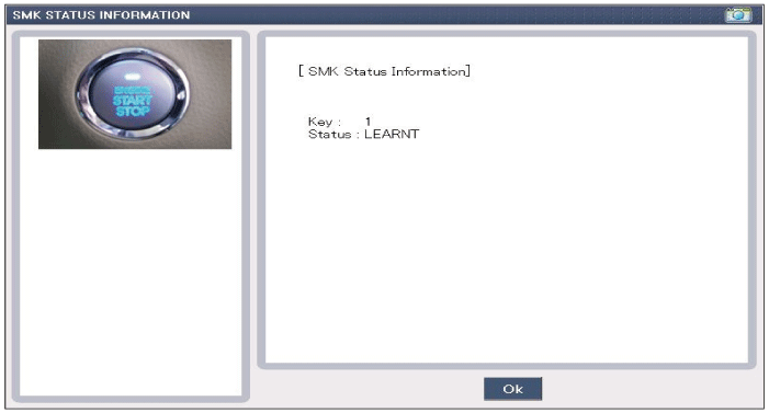
- Connect the GDS cable to the data link connector in the driver's side lower panel.
- After IGN ON, select "Neutralization Mode".
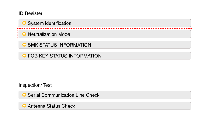
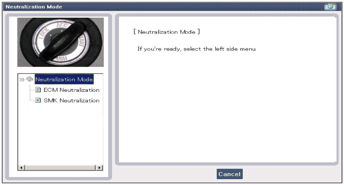
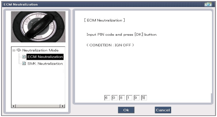
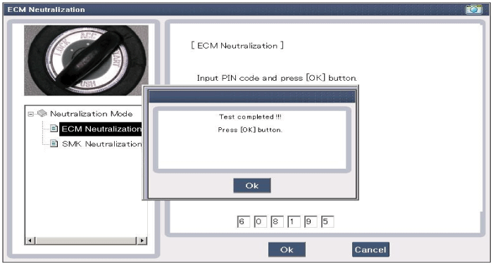
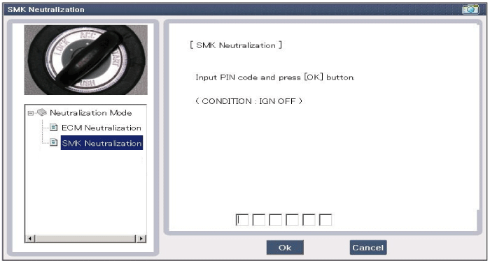

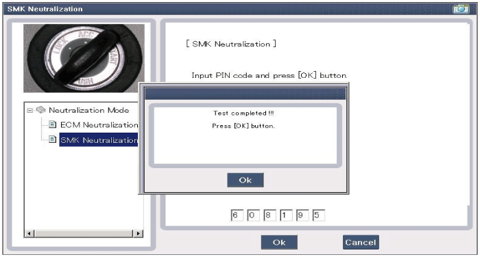
| No | Item Name | Unit |
| 1 | SSB Switch 2 | - |
| 2 | ACC | - |
| 3 | IGN1 | - |
| 4 | Shift lever in "P" position | - |
| 5 | Brake Switch | - |
| 6 | FL door lock button | - |
| 7 | FR door lock button | - |
| 8 | Trunk lid switch | - |
| 9 | Battery Voltage | - |
| 10 | Generator voltage | - |
| 11 | KEY out indicator lamp | - |
| 12 | Immobilizer lamp | - |
| 13 | External Buzzer | - |
Actuator List
| No. | Item Name | Condition |
| 1 | Immobilizer Indicator Lamp | Ignition ON Engine OFF |
| 2 | External Buzzer | Ignition ON Engine OFF |
| 3 | Internal antenna 1 active | Ignition ON Engine OFF |
| 4 | Internal antenna 2 active | Ignition ON Engine OFF |
| 5 | Interior Antenna 3 Active | Ignition ON Engine OFF |
| 6 | Bumper antenna active | Ignition ON Engine OFF |
| 7 | DRV DR antenna active | Ignition ON Engine OFF |
| 8 | AST DR antenna active | Ignition ON Engine OFF |
Test yourself
A quick Kia Sorento Owner's Manual quiz: every answer comes with an explanation and a link to the manual page.
Was this page helpful?