Component parts
Component Parts Location
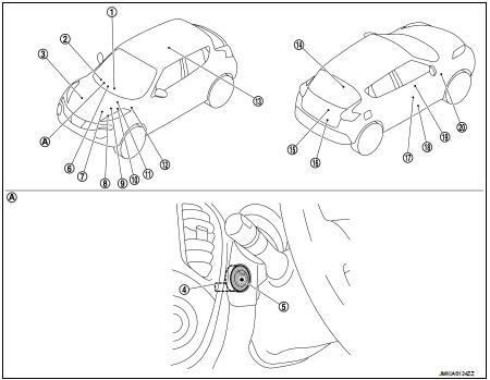
1. Remote keyless entry receiver Refer to DLK-21, "Component Parts Location" (With super lock) or DLK-198, "Component Parts Location" (Without super lock). 2. Combination meter Refer to MWI-4, "METER SYSTEM : Component Parts Location". 3. Stop lamp switch Refer to BRC-9, "Component Parts Location" (Without ESP) or BRC-97, "Component Parts Location" (With ESP). 4. NATS antenna amp.
5. Push-button ignition switch 6. Inside key antenna (instrument center) Refer to DLK-21, "Component Parts Location" (With super lock) or DLK-198, "Component Parts Location" (Without super lock). 7. Transmission range switch Refer to TM-131, "CVT CONTROL SYSTEM : Component Parts Location" (CVT: RE0F10B) or TM-314, "CVT CONTROL SYSTEM : Component Parts Location" (CVT: RE0F11A). 8. ECM Refer to EC-25, "ENGINE CONTROL SYSTEM : Component Parts Location" (MR16DDT), EC-455, "ENGINE CONTROL SYSTEM : Component Parts Location" (HR16DE) or EC-813, "Component Parts Location" (K9K). 9. IPDM E/R Refer to PCS-5, "Component Parts Location
10. TCM Refer to TM-131, "CVT CONTROL SYSTEM : Component Parts Location" (CVT: RE0F10B) or TM-314, "CVT CONTROL SYSTEM : Component Parts Location" (CVT: RE0F11A). 11. ABS actuator and electric unit (control unit) Refer to BRC-9, "Component Parts Location" (Without ESP) or BRC-97, "Component Parts Location" (With ESP). 12. BCM Refer to BCS-6, "BODY CONTROL SYSTEM : Component Parts Location". 13. Inside key antenna (console) Refer to DLK-21, "Component Parts Location" (With super lock) or DLK-198, "Component Parts Location" (Without super lock). 14. Inside key antenna (luggage room) Refer to DLK-21, "Component Parts Location" (With super lock) or DLK-198, "Component Parts Location" (Without super lock).
15. Back door request switch 16. Back door opener assembly 17. Front door lock assembly 18. Front door switch (driver side) 19. Front door request switch (driver side)
20. Clutch interlock switch
A. Behind push-button ignition switch
Component Description
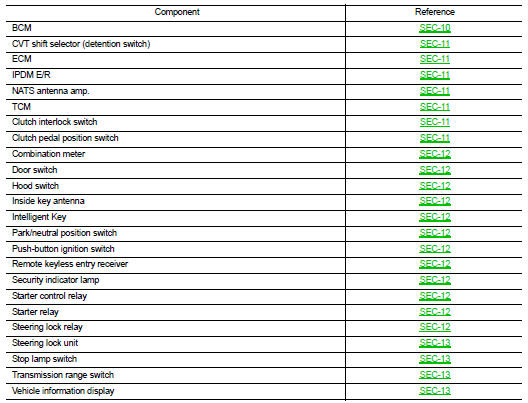
BCM
BCM controls INTELLIGENT KEY SYSTEM (ENGINE START FUNCTION), NISSAN VEHICLE IMMOBILIZER SYSTEM-NATS [NVIS (NATS)], and VEHICLE SECURITY SYSTEM.
BCM performs the ID verification between BCM and Intelligent Key when the Intelligent Key is carried into the detection area of inside key antenna, and push-button ignition switch is pressed. If the ID verification result is OK, push-button ignition switch operation is available.
Then, when the power supply position is turned ON, BCM performs ID verification between BCM and ECM. If the ID verification result is OK, ECM can start engine.
CVT Shift Selector (Detention Switch)
Detention switch detects that CVT shift selector is in the P position, and then transmits the signal to BCM and IPDM E/R.
BCM confirms the CVT shift selector position with the following 5 signals.
• P position signal from CVT shift selector (detention switch) • P/N position signal from transmission range switch • P position signal from IPDM E/R (CAN) • P/N position signal from IPDM E/R (CAN) • P/N position signal from TCM (CAN)
IPDM E/R confirms the CVT shift selector position with the following 3 signals.
• P position signal from CVT shift selector (detention switch) • P/N position signal from transmission range switch • P/N position signal from BCM (CAN)
ECM
ECM controls the engine.
When power supply position is turned ON, BCM starts communication with ECM and performs the ID verification between BCM and ECM.
If the verification result is OK, the engine can start. If the verification result is NG, the engine can not start.
IPDM E/R
IPDM E/R has steering lock relay, starter relay and starter control relay inside. Steering lock relay is used for the steering lock/unlock function. Starter relay and starter control relay are used for the engine starting function.
IPDM E/R controls these relays while communicating with BCM.
NATS Antenna Amp
The ID verification is performed between BCM and transponder in Intelligent Key via NATS antenna amp.
when Intelligent Key backside is contacted to push-button ignition switch in case that Intelligent Key battery is discharged. If the ID verification result is OK, the release of steering lock and the operation of starting engine is available.
TCM
TCM transmits the shift position signal (P/N position) to BCM and IPDM E/R via CAN communication.
BCM confirms the CVT shift selector position with the following 5 signals.
• P position signal from CVT shift selector (detention switch) • P/N position signal from transmission range switch • P position signal from IPDM E/R (CAN) • P/N position signal from IPDM E/R (CAN) • P/N position signal from TCM (CAN)
IPDM E/R confirms the CVT shift selector position with the following 3 signals.
• P position signal from CVT shift selector (detention switch) • P/N position signal from transmission range switch • P/N position signal from BCM (CAN)
Clutch Interlock Switch
Clutch interlock switch detects that clutch pedal is depressed, then provides power source to starter control relay and starter relay, and transmits ON/OFF signal to BCM.
Clutch Pedal Position Switch
Clutch pedal position switch detects that clutch pedal is depressed, and then transmits ON/OFF signal to ECM. ECM transmits the clutch pedal position switch signal to BCM via CAN communication.
Combination Meter
Combination meter transmits the vehicle speed signal to BCM via CAN communication.
BCM also receives the vehicle speed signal from ABS actuator and electric unit (control unit) via CAN communication.
BCM compares both signals to detect the vehicle speed.
Door Switch
Door switch detects door open/close condition and then transmits ON/OFF signal to BCM.
Hood Switch
Hood switch detects that hood is open, and then transmits the signal to IPDM E/R. IPDM E/R transmits hood switch signal to BCM via CAN communication.
Inside Key Antenna
Inside key antenna detects whether Intelligent Key is inside the vehicle, and transmits the signal to BCM.
Three inside key antennas are installed in the instrument center, console and luggage room.
Intelligent Key
Each Intelligent key has an individual electronic ID, and transmits the ID signal by request from BCM.
Carrying the Intelligent Key whose ID is registered in BCM, the driver can performs door lock/unlock operation and push-button ignition switch operation.
Park/Neutral Position (PNP) Switch
Park/neutral position (PNP) switch detects that shift lever is in the neutral position, and then transmits ON/OFF signal to BCM.
Push-button Ignition Switch
Push-button ignition switch detects that push-button is pressed, and then transmits the signal to BCM. BCM changes the power supply position with the operation of push-button ignition switch. BCM maintains the power supply position status while push-button is not operated.
Remote Keyless Entry Receiver
Remote keyless entry receiver receives each button operation signal and electronic key ID signal from Intelligent Key, and then transmits the signal to BCM.
Security Indicator Lamp
Security indicator lamp is located on combination meter.
Security indicator lamp blinks when power supply position is any position other than ON to warn that NISSAN VEHICLE IMMOBILIZER SYSTEM-NATS [NVIS (NATS)] is on board.
Starter Control Relay
Engine starting system functions by controlling both starter relay and starter control relay.
Both relays are integrated in IPDM E/R. Starter relay is controlled by BCM, and starter control relay is controlled by IPDM E/R on request from BCM.
IPDM E/R transmits starter relay and starter control relay status signal to BCM via CAN communication.
Starter Relay
Engine starting system functions by controlling both starter relay and starter control relay.
Both relays are integrated in IPDM E/R. Starter relay is controlled by BCM, and starter control relay is controlled by IPDM E/R on request from BCM.
IPDM E/R transmits starter relay and starter control relay status signal to BCM via CAN communication.
Steering Lock Relay
Steering lock relay is integrated in IPDM E/R, and supplies power source to steering lock unit.
When IPDM E/R receives the steering lock relay ON request signal from BCM, IPDM E/R turns ON steering lock relay and then transmits the steering lock relay condition signal to BCM.
Steering Lock Unit
Steering lock unit performs steering lock/unlock operation on request from BCM, and power source is supplied from steering lock relay integrated in IPDM E/R.
When push-button ignition switch is pressed while the Intelligent Key is inside the vehicle, BCM performs the ID verification with steering lock unit. Steering lock unit releases the steering lock based on the result of the ID verification.
Steering lock unit has 2 switches (steering lock status switch and steering unlock status switch) inside. BCM judges the steering lock/unlock condition by comparing these switch signals and steering lock unit status signal transmitted from IPDM E/R via CAN communication.
Stop Lamp Switch
Stop lamp switch detects that brake pedal is depressed, and then transmits the signal to BCM.
Transmission Range Switch
Transmission range switch is integrated in CVT assembly, and detects the CVT shift selector position.
TCM receives the transmission range switch signal and then transmits the P/N position signal to BCM and IPDM E/R.
BCM confirms the CVT shift selector position with the following 5 signals.
• P position signal from CVT shift selector (detention switch) • P/N position signal from transmission range switch • P position signal from IPDM E/R (CAN) • P/N position signal from IPDM E/R (CAN) • P/N position signal from TCM (CAN)
IPDM E/R confirms the CVT shift selector position with the following 3 signals.
• P position signal from CVT shift selector (detention switch) • P/N position signal from transmission range switch • P/N position signal from BCM (CAN)
Vehicle Information Display
Vehicle information display is integrated in combination meter.
Various information and warnings regarding to the Intelligent Key System are displayed.