Heater & Air Conditioning System HR16DE

Compressor

In this manual: Heater & Air Conditioning System HR16DE
Foreword — 1General information — 45Engine Mechanical MR16DDT — 61Engine Mechanical HR16DE — 52Engine Mechanical K9K — 46Engine Lubrication System MR16DDT — 18Engine Lubrication System HR16DE — 14Engine Lubrication System K9K — 11Engine Cooling System MR16DDT — 28Engine Cooling System HR16DE — 29Engine Cooling System K9K — 24Engine Control System MR16DDT — 163Engine Control System HR16DE — 115Engine Control System K9K — 129Fuel System MR16DDT — 13Fuel system HR16DE — 11Fuel system K9K — 12Exhaust system MR16DDT — 7Exhaust system HR16DE — 10Exhaust system K9K — 7Starting system — 24Accelerator control system — 6Clutch — 25Driveline transfer: TY21B — 77Driveline rear propeller Shaft: 3Fφ16-ETJ75 — 12Driveline rear final drive: RTVS — 31Transaxle & transmission 5MT: RS5F92R — 31Transaxle & transmission 6MT: RS6F94R — 30Transaxle & transmission CVT: RE0F10B — 93Transaxle & transmissioN CVT: RE0F11A — 103Front Axle MR16DDT — 18Front Axle HR16DE — 17Front Axle K9K — 17Rear Axle 2WD — 6Rear Axle 4WD — 13Front Suspension — 21Rear Suspension 2WD — 13Rear Suspension 4WD — 17Road Wheels & Tires — 6Brake System LHD — 24Brake System RHD — 24Parking Brake System — 8Brake Control System without ESP — 44Brake Control System with ESP — 63Steering System — 14Steering Control System — 27Seat Belt — 8SRS Airbag — 24SRS Airbag Control System — 93Ventilation System — 11Heater & Air Conditioning System HR16DE — 28Heater & Air Conditioning System MR16DDT — 28Heater & Air Conditioning Control System Type 1 — 49Heater & Air Conditioning Control System Type 2 — 51Heater & Air Conditioning Control System Type 3 — 32Heater & Air Conditioning Control System Type 4 — 40Heater & Air Conditioning Control System Type 5 — 21Interior — 16Instrument Panel — 10Seat — 18Door & Lock Type 1 — 83Door & Lock type 2 — 80Door & Lock type 3 — 65Door & Lock type 4 — 60Security Control System with intelligent key system — 82Security Control System without intelligent key system — 41Glass & Window System — 15Power Window Control System — 28Body Repair — 13Exterior — 20Mirrors — 26Exterior Lighting System Halogen type — 51Interior Lighting System — 24Wiper & Washer — 45Defogger — 31Horn — 4Power Outlet — 4Body Control System With intelligent key system — 21Body Control System Without intelligent key system — 23LAN system can fundamental — 6LAN system can — 31LAN System can system (type 1) — 1LAN System can system (type 2) — 1LAN System can system (type 3) — 1LAN System can system (type 4) — 1LAN System can system (type 5) — 1LAN System can system (type 6) — 1LAN System can system (type 7) — 2LAN System can system (type 8) — 1LAN System can system (type 9) — 1LAN System can system (type 10) — 1LAN System can system (type 11) — 1Power Control System IPDM E/R (with I-key) — 14Power Control System IPDM E/R (without I-key) — 14Power Control System Power distribution system — 25Charging System — 22Power Supply, Ground & Circuit Elements — 20Meter, Warning Lamp & Indicator — 33Warning Chime System — 22Audio, Visual & Navigation System Audio without navigation — 30Audio, Visual & Navigation System Audio with navigation — 33Audio, Visual & Navigation System NISSAN dynamic control system — 22Cruise Control System — 1Drive Mode System — 10Maintenance — 14
~3min read

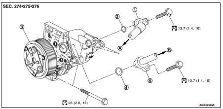
Exploded View

REMOVAL

1. High-pressure flexible hose

1. High-pressure flexible hose 2. O-ring
3. Compressor
4. O-ring
5. Low-pressure flexible hose

A. To condenser
B. To evaporator

DISASSEMBLY: N·m (kg-m, ft-lb)


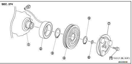
DISASSEMBLY

1. Compressor unit

1. Compressor unit 2. Field coil 3. Snap ring 4. Pulley assembly 5. Snap ring 6. Shim 7. Clutch disc

Compressor : Removal and Installation: N·m (kg-m, ft-lb)


Compressor : Removal and Installation

CAUTION:
Perform lubricant return operation before each refrigeration system disassembly. However, if a large amount of refrigerant or lubricant is detected, never perform lubricant return operation. Refer to HA- 23, "Perform Lubricant Return Operation".

REMOVAL

1. Use a refrigerant collecting equipment (for HFC-134a) to discharge the refrigerant. Refer to HA-21, "Recycle Refrigerant".

2. Remove mounting bolts, and then disconnect low-pressure flexible hose and high-pressure flexible hose from the compressor.

CAUTION:
Cap or wrap the joint of the A/C piping and compressor with suitable material such as vinyl tape to avoid the entry of air.
3. Remove drive belt. Refer to EM-155, "Removal and Installation". 4. Disconnect compressor (magnet clutch) connector.

5. Remove mounting bolts, and then remove compressor form the vehicle.

INSTALLATION

Note the following items, and then install in the reverse order of removal.

CAUTION:
• Replace O-rings with new ones. Then apply compressor oil to them when installing. • Perform lubricant adjusting procedure before installing new compressor. Refer to HA-23, "Perform Lubricant Return Operation". • Check for leakages when recharging refrigerant. Refer to HA-19, "Leak Test".

• Check tension of the drive belt after installing compressor. Refer to EM-154, "Checking"

.

Magnet clutch : Removal and Installation of Compressor Clutch

REMOVAL

Overhaul
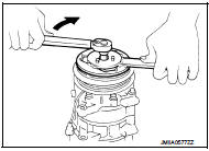
1. When removing center bolt, hold clutch disc with clutch disc wrench (SST:KV99232340) (A).

2. Remove clutch disc.

2. Remove clutch disc. 3. Remove snap ring using external snap ring pliers.

4. Position center pulley puller on the end of the drive shaft, and remove pulley assembly using any commercially available pulley puller.

To prevent pulley groove from being deformed, puller claws should be positioned into the edge of the pulley assembly.

5. Disconnect harness connector from compressor unit.

6. Remove snap ring using external snap ring pliers, and then remove field coil.

INSTALLATION

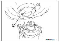
1. Install field coil (1).

Be sure to align the coil’s pin (2) with the hole in the compressor’s front head.

2. Install field coil harness clip.
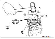
3. Install pulley assembly (1) using pulley installer

3. Install pulley assembly (1) using pulley installer (SST:KV99106200) (A) and a hand press, and then install snap ring (2) using snap ring pliers.
4. Install clutch disc on drive shaft, together with original shim(s). Press

4. Install clutch disc on drive shaft, together with original shim(s). Press clutch disc down by hand.

5. Tighten center bolt to the specified torque while fixing clutch disc not to rotate using a clutch disc wrench (SST:KV99232340).

After tightening the bolt, check that the pulley rotates smoothly.
Break-in Operation

Break-in Operation
When replacing compressor clutch assembly, always perform the break-in operation, by engaging and disengaging the clutch approximately 30-times. Break-in operation increases the level of transmitted torque.

Inspection

CHECK DISC TO PULLEY CLEARANCE

Check the clearance (B) between pulley assembly (1) and clutch disc (2) along the entire periphery with a feeler gauge (A).

Clearance : Refer to HA-58, "Compressor".

Replace compressor if specified clearance is not obtained.

Cooler pipe and hose