Engine Control System HR16DE

ECU diagnosis information

In this manual: Engine Control System HR16DE
Foreword — 1General information — 45Engine Mechanical MR16DDT — 61Engine Mechanical HR16DE — 52Engine Mechanical K9K — 46Engine Lubrication System MR16DDT — 18Engine Lubrication System HR16DE — 14Engine Lubrication System K9K — 11Engine Cooling System MR16DDT — 28Engine Cooling System HR16DE — 29Engine Cooling System K9K — 24Engine Control System MR16DDT — 163Engine Control System HR16DE — 115Engine Control System K9K — 129Fuel System MR16DDT — 13Fuel system HR16DE — 11Fuel system K9K — 12Exhaust system MR16DDT — 7Exhaust system HR16DE — 10Exhaust system K9K — 7Starting system — 24Accelerator control system — 6Clutch — 25Driveline transfer: TY21B — 77Driveline rear propeller Shaft: 3Fφ16-ETJ75 — 12Driveline rear final drive: RTVS — 31Transaxle & transmission 5MT: RS5F92R — 31Transaxle & transmission 6MT: RS6F94R — 30Transaxle & transmission CVT: RE0F10B — 93Transaxle & transmissioN CVT: RE0F11A — 103Front Axle MR16DDT — 18Front Axle HR16DE — 17Front Axle K9K — 17Rear Axle 2WD — 6Rear Axle 4WD — 13Front Suspension — 21Rear Suspension 2WD — 13Rear Suspension 4WD — 17Road Wheels & Tires — 6Brake System LHD — 24Brake System RHD — 24Parking Brake System — 8Brake Control System without ESP — 44Brake Control System with ESP — 63Steering System — 14Steering Control System — 27Seat Belt — 8SRS Airbag — 24SRS Airbag Control System — 93Ventilation System — 11Heater & Air Conditioning System HR16DE — 28Heater & Air Conditioning System MR16DDT — 28Heater & Air Conditioning Control System Type 1 — 49Heater & Air Conditioning Control System Type 2 — 51Heater & Air Conditioning Control System Type 3 — 32Heater & Air Conditioning Control System Type 4 — 40Heater & Air Conditioning Control System Type 5 — 21Interior — 16Instrument Panel — 10Seat — 18Door & Lock Type 1 — 83Door & Lock type 2 — 80Door & Lock type 3 — 65Door & Lock type 4 — 60Security Control System with intelligent key system — 82Security Control System without intelligent key system — 41Glass & Window System — 15Power Window Control System — 28Body Repair — 13Exterior — 20Mirrors — 26Exterior Lighting System Halogen type — 51Interior Lighting System — 24Wiper & Washer — 45Defogger — 31Horn — 4Power Outlet — 4Body Control System With intelligent key system — 21Body Control System Without intelligent key system — 23LAN system can fundamental — 6LAN system can — 31LAN System can system (type 1) — 1LAN System can system (type 2) — 1LAN System can system (type 3) — 1LAN System can system (type 4) — 1LAN System can system (type 5) — 1LAN System can system (type 6) — 1LAN System can system (type 7) — 2LAN System can system (type 8) — 1LAN System can system (type 9) — 1LAN System can system (type 10) — 1LAN System can system (type 11) — 1Power Control System IPDM E/R (with I-key) — 14Power Control System IPDM E/R (without I-key) — 14Power Control System Power distribution system — 25Charging System — 22Power Supply, Ground & Circuit Elements — 20Meter, Warning Lamp & Indicator — 33Warning Chime System — 22Audio, Visual & Navigation System Audio without navigation — 30Audio, Visual & Navigation System Audio with navigation — 33Audio, Visual & Navigation System NISSAN dynamic control system — 22Cruise Control System — 1Drive Mode System — 10Maintenance — 14
~3min read
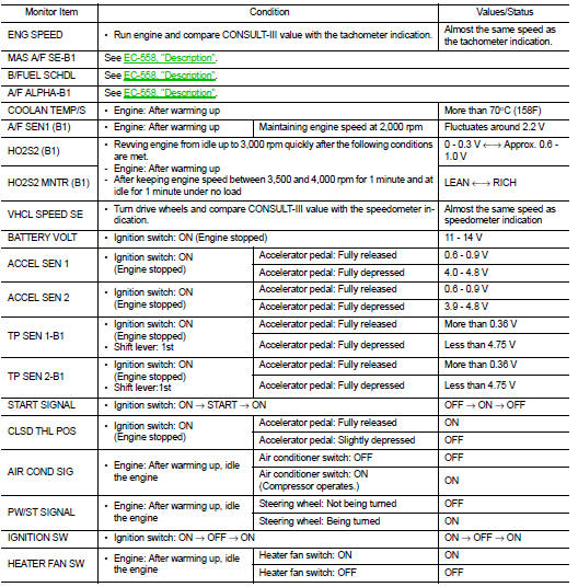
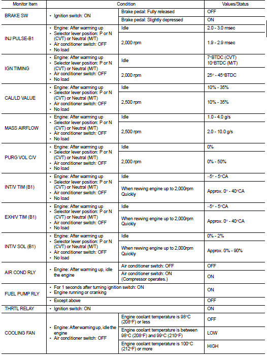
ECM Reference Value

VALUES ON THE DIAGNOSIS TOOL

Remarks:
• Specification data are reference values. • Specification data are output/input values which are detected or supplied by the ECM at the connector.

*Specification data may not be directly related to their components signals/values/operations.

i.e. Adjust ignition timing with a timing light before monitoring IGN TIMING, because the monitor may show the specification data in spite of the ignition timing not being adjusted to the specification data. This IGN TIMING monitors the data calculated by the ECM according to the signals input from the camshaft position sensor and other ignition timing related sensors.
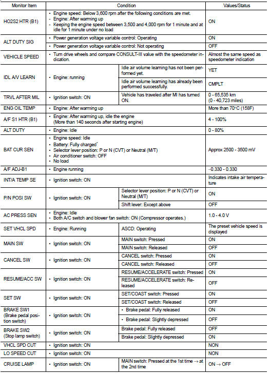

*: Accelerator pedal position sensor 2 signal and throttle position sensor 2

*: Accelerator pedal position sensor 2 signal and throttle position sensor 2 signal are converted by ECM internally. Thus, they differ from ECM terminals voltage signal.

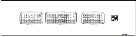
TERMINAL LAYOUT
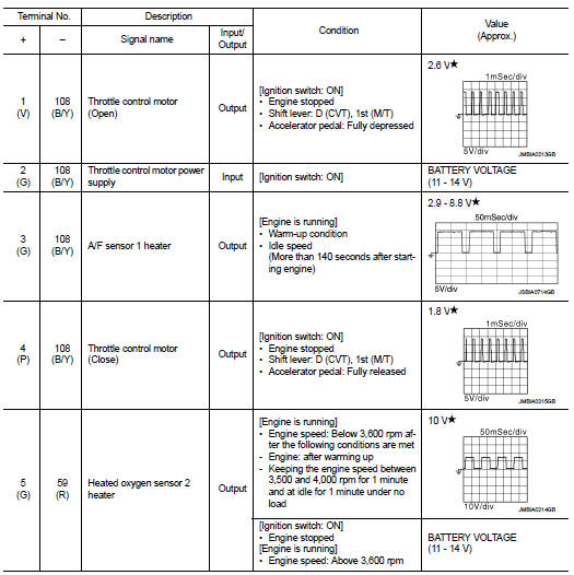
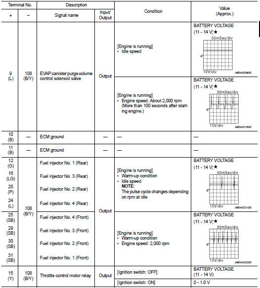
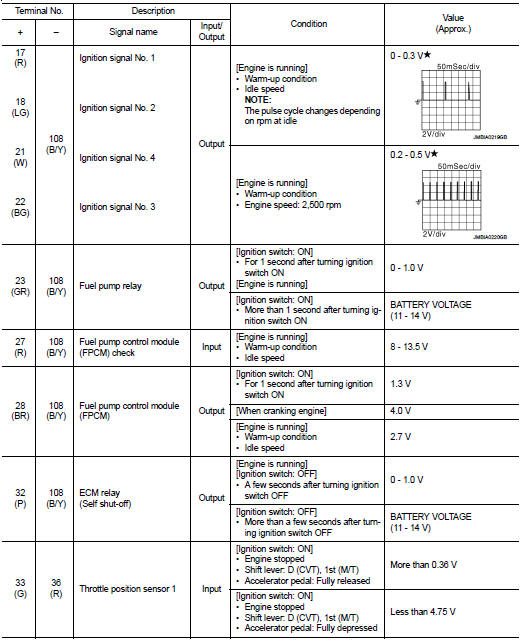
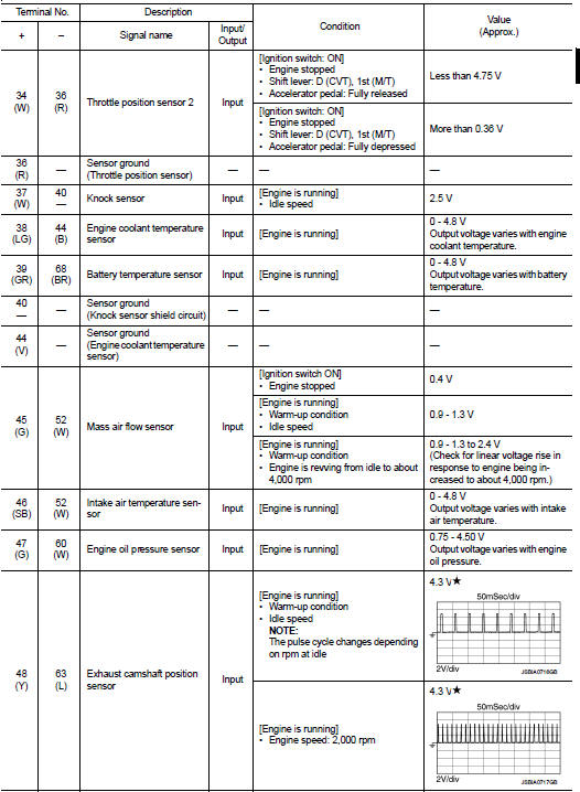
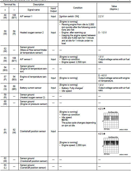
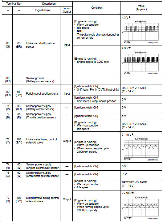
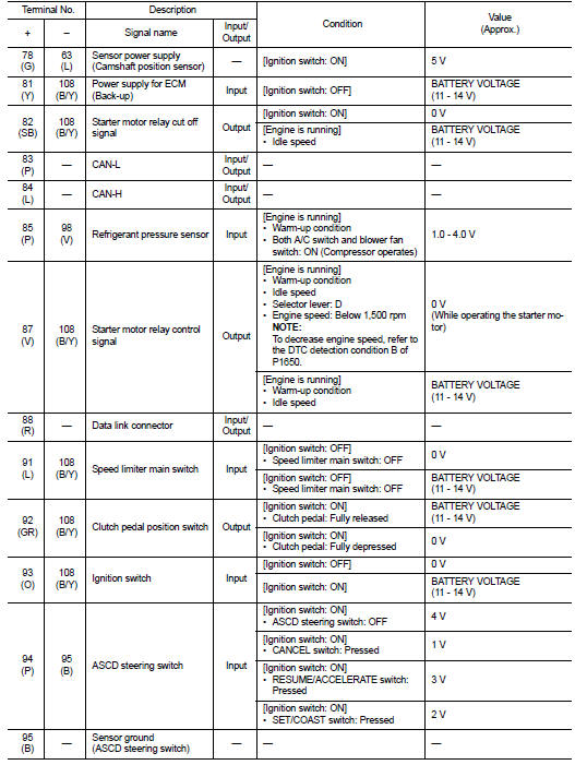
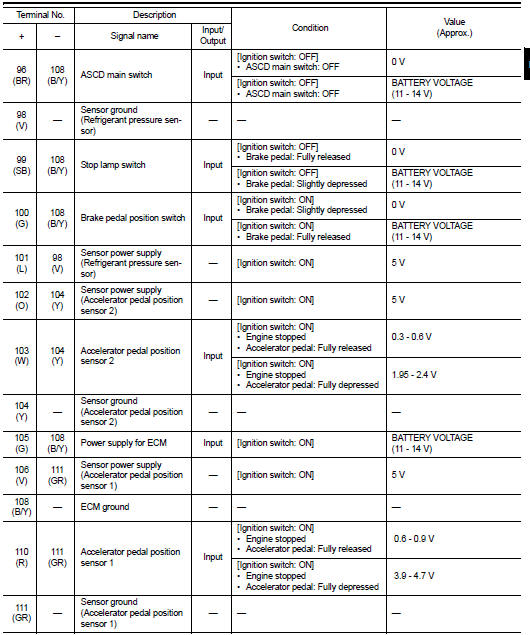
PHYSICAL VALUES

PHYSICAL VALUES

NOTE

:

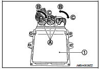
• ECM is located in the engine room left side near battery. • When disconnecting ECM harness connector (A), loosen (C) it with levers as far as they will go as shown in the figure.

- ECM (1)
- Fasten (B)

• Connect a break-out box and harness adapter between the ECM and ECM harness connector. - Use extreme care not to touch 2 pins at one time.

- Data is for comparison and may not be exact.

• Specification data are reference values and are measured between each terminals.

• Pulse signal is measured by CONSULT-III.


: Average voltage for pulse

signal (Actual pulse signal can be confirmed by oscilloscope.): Average voltage for pulse
signal (Actual pulse signal can be confirmed by oscilloscope.) *: Before measuring the terminal voltage, confirm that the battery is fully charged. Refer to PG-111, "How to Handle Battery".

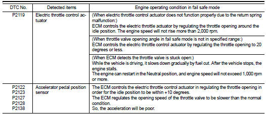
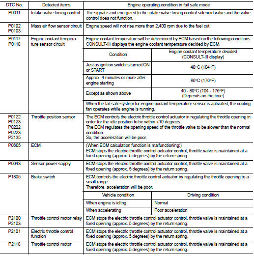
Fail Safe

NON DTC RELATED ITEM

DTC RELATED ITEM
DTC RELATED ITEM


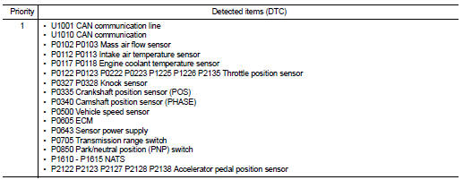
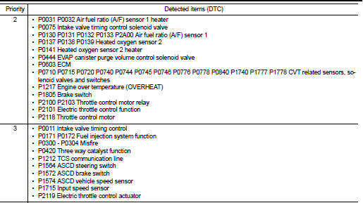
DTC Inspection Priority Chart

DTC Inspection Priority Chart

If some DTCs are displayed at the same time, perform inspections one by one based on the following priority chart.
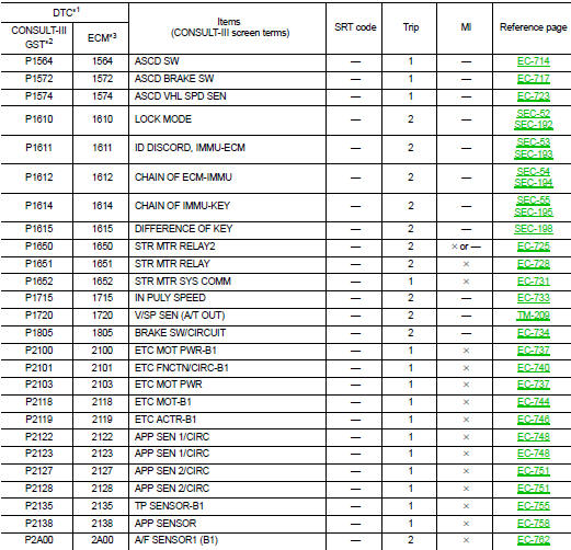
DTC Index

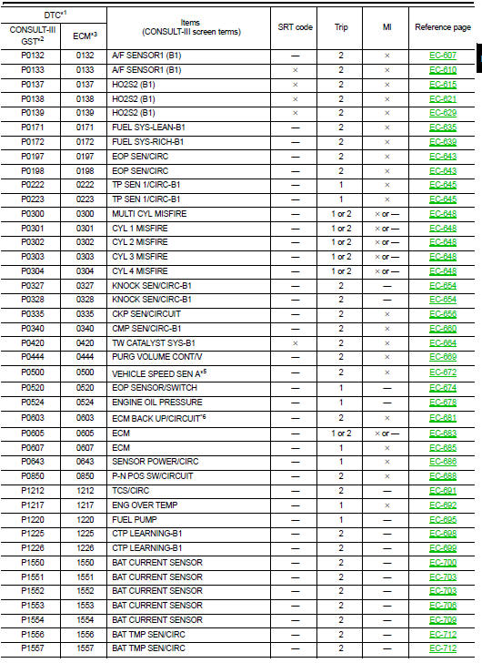
DTC Index


*1: 1st trip DTC No. is the same as DTC No.

*1: 1st trip DTC No. is the same as DTC No. *2: This number is prescribed by SAE J1979/ ISO 15031-5. *3: In Diagnostic Test Mode II (Self-diagnostic results), this number is controlled by NISSAN. *4: The troubleshooting for this DTC needs CONSULT-III. *5: When the fail-safe operations for both self-diagnoses occur, the MI illuminates.

*6: This self-diagnosis is not for ECM power supply circuit, even though “ECM BACK UP/CIRCUIT” is displayed on CONSULT-III screen.

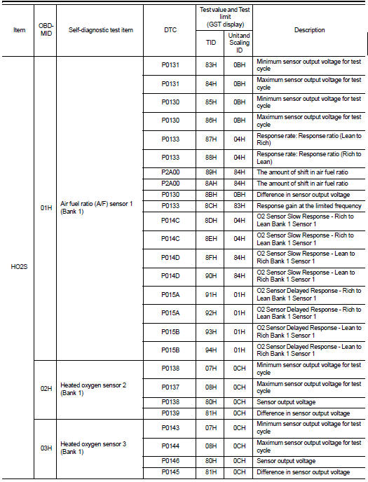
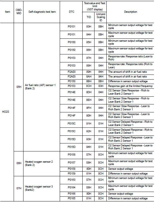
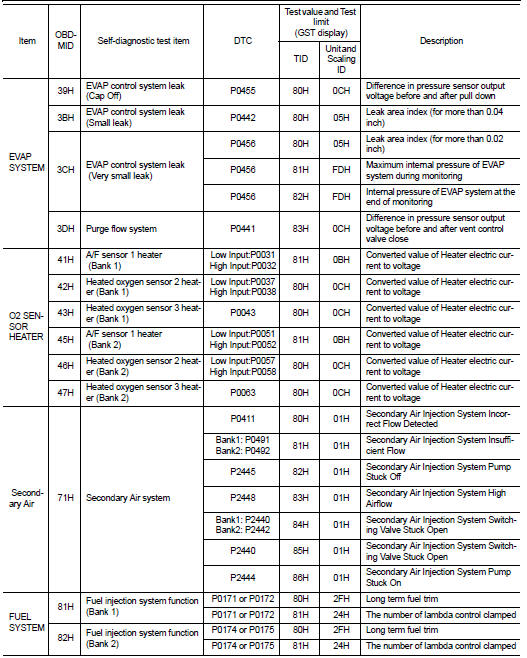
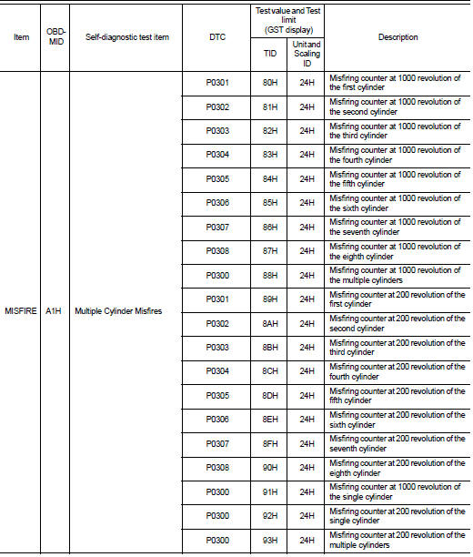
Test Value and Test Limit

The following is the information specified in Service $06 of SAE J1979/ISO 15031-5.

The test value is a parameter used to determine whether a system/circuit diagnostic test is OK or NG while being monitored by the ECM during self-diagnosis. The test limit is a reference value which is specified as the maximum or minimum value and is compared with the test value being monitored.

These data (test value and test limit) are specified by On Board Monitor ID (OBDMID), Test ID (TID), Unit and Scaling ID and can be displayed on the GST screen.

The items of the test value and test limit will be displayed with GST screen which items are provided by the ECM. (e.g., if bank 2 is not applied on this vehicle, only the items of bank 1 are displayed)


Wiring diagram