Brake System LHD

Front disc brake

In this manual: Brake System LHD
Foreword — 1General information — 45Engine Mechanical MR16DDT — 61Engine Mechanical HR16DE — 52Engine Mechanical K9K — 46Engine Lubrication System MR16DDT — 18Engine Lubrication System HR16DE — 14Engine Lubrication System K9K — 11Engine Cooling System MR16DDT — 28Engine Cooling System HR16DE — 29Engine Cooling System K9K — 24Engine Control System MR16DDT — 163Engine Control System HR16DE — 115Engine Control System K9K — 129Fuel System MR16DDT — 13Fuel system HR16DE — 11Fuel system K9K — 12Exhaust system MR16DDT — 7Exhaust system HR16DE — 10Exhaust system K9K — 7Starting system — 24Accelerator control system — 6Clutch — 25Driveline transfer: TY21B — 77Driveline rear propeller Shaft: 3Fφ16-ETJ75 — 12Driveline rear final drive: RTVS — 31Transaxle & transmission 5MT: RS5F92R — 31Transaxle & transmission 6MT: RS6F94R — 30Transaxle & transmission CVT: RE0F10B — 93Transaxle & transmissioN CVT: RE0F11A — 103Front Axle MR16DDT — 18Front Axle HR16DE — 17Front Axle K9K — 17Rear Axle 2WD — 6Rear Axle 4WD — 13Front Suspension — 21Rear Suspension 2WD — 13Rear Suspension 4WD — 17Road Wheels & Tires — 6Brake System LHD — 24Brake System RHD — 24Parking Brake System — 8Brake Control System without ESP — 44Brake Control System with ESP — 63Steering System — 14Steering Control System — 27Seat Belt — 8SRS Airbag — 24SRS Airbag Control System — 93Ventilation System — 11Heater & Air Conditioning System HR16DE — 28Heater & Air Conditioning System MR16DDT — 28Heater & Air Conditioning Control System Type 1 — 49Heater & Air Conditioning Control System Type 2 — 51Heater & Air Conditioning Control System Type 3 — 32Heater & Air Conditioning Control System Type 4 — 40Heater & Air Conditioning Control System Type 5 — 21Interior — 16Instrument Panel — 10Seat — 18Door & Lock Type 1 — 83Door & Lock type 2 — 80Door & Lock type 3 — 65Door & Lock type 4 — 60Security Control System with intelligent key system — 82Security Control System without intelligent key system — 41Glass & Window System — 15Power Window Control System — 28Body Repair — 13Exterior — 20Mirrors — 26Exterior Lighting System Halogen type — 51Interior Lighting System — 24Wiper & Washer — 45Defogger — 31Horn — 4Power Outlet — 4Body Control System With intelligent key system — 21Body Control System Without intelligent key system — 23LAN system can fundamental — 6LAN system can — 31LAN System can system (type 1) — 1LAN System can system (type 2) — 1LAN System can system (type 3) — 1LAN System can system (type 4) — 1LAN System can system (type 5) — 1LAN System can system (type 6) — 1LAN System can system (type 7) — 2LAN System can system (type 8) — 1LAN System can system (type 9) — 1LAN System can system (type 10) — 1LAN System can system (type 11) — 1Power Control System IPDM E/R (with I-key) — 14Power Control System IPDM E/R (without I-key) — 14Power Control System Power distribution system — 25Charging System — 22Power Supply, Ground & Circuit Elements — 20Meter, Warning Lamp & Indicator — 33Warning Chime System — 22Audio, Visual & Navigation System Audio without navigation — 30Audio, Visual & Navigation System Audio with navigation — 33Audio, Visual & Navigation System NISSAN dynamic control system — 22Cruise Control System — 1Drive Mode System — 10Maintenance — 14
~3min read

Brake pad : Inspection and Adjustment

INSPECTION

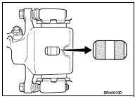
Check brake pad wear thickness from an inspection hole on cylinder body. Check using a scale if necessary.

Wear thickness : Refer to BR-71, "Front Disc Brake".
ADJUSTMENT

ADJUSTMENT

Burnish contact surfaces between disc rotor and brake pads according to the following procedure after refinishing or replacing brake pads, or if a soft pedal occurs at very low mileage.

CAUTION:
• Be careful of vehicle speed because the brake does not operate firmly/securely until pads and disc rotor are securely fitted.

• Only perform this procedure under safe road and traffic conditions. Use extreme caution.

1. Drive vehicle on straight, flat road. 2. Depress brake pedal with the power to stop vehicle within 3 to 5 seconds until the vehicle stops. 3. Drive without depressing brake for a few minutes to cool the brake.

4. Repeat steps 1 to 3 until pad and disc rotor are securely fitted.

Disc rotor : Inspection and Adjustment

INSPECTION

Appearance
Check surface of disc rotor for uneven wear, cracks, and serious damage. Replace it if necessary.

• MR16DDT: Refer to FAX-11, "Removal and Installation". • HR16DE: Refer to FAX-43, "Removal and Installation".

• K9K: Refer to FAX-68, "Removal and Installation".

Runout
1. Fix the disc rotor to the wheel hub and bearing assembly with wheel nuts (2 points at least).

2. Check the wheel bearing axial end play before the inspection.

• MR16DDT: Refer to FAX-9, "Inspection". • HR16DE: Refer to FAX-41, "Inspection".

• K9K: Refer to FAX-66, "Inspection".

3. Inspect the runout with a dial indicator to measure at 10 mm (0.39 in) inside the disc edge.

Runout (with it attached to the vehicle) : Refer to BR-71, "Front Disc Brake".
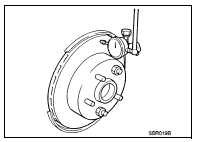
4. Find the installation position that has a minimum runout by shifting the

4. Find the installation position that has a minimum runout by shifting the disc rotor-to-wheel hub and bearing assembly installation position by one hole at a time if the runout exceeds the limit value.

• Refinish the disc rotor if the runout is outside the limit even after performing the above operation.

CAUTION:
• Check in advance that the thickness of the disc rotor is wear thickness + 0.3 mm (0.012 in) or more. • If the thickness is less than wear thickness + 0.3 mm (0.012 in), replace the disc rotor. - MR16DDT: Refer to FAX-11, "Removal and Installation". - HR16DE: Refer to FAX-43, "Removal and Installation".

- K9K: Refer to FAX-68, "Removal and Installation".

Wear thickness : Refer to BR-71, "Front Disc Brake".

Thickness
Check the thickness of the disc rotor using a micrometer. Replace the disc rotor if the thickness is below the wear limit.

• MR16DDT: Refer to FAX-11, "Removal and Installation". • HR16DE: Refer to FAX-43, "Removal and Installation".

• K9K: Refer to FAX-68, "Removal and Installation".

Wear thickness : Refer to BR-71, "Front Disc Brake".

ADJUSTMENT

ADJUSTMENT

Burnish contact surfaces between disc rotors and brake pads according to the following procedure after refinishing or replacing disc rotor, or if a soft pedal occurs at very low mileage.

CAUTION:
• Be careful of vehicle speed because the brake does not operate firmly/securely until pad and disc rotor are securely fitted.

• Only perform this procedure under safe road and traffic conditions. Use extreme caution.

1. Drive vehicle on straight, flat road. 2. Depress brake pedal with the power to stop vehicle within 3 to 5 seconds until the vehicle stops. 3. Drive without depressing brake for a few minutes to cool the brake.

4. Repeat steps 1 to 3 until pad and disc rotor are securely fitted.