Engine Control System K9K

On board diagnostic (OBD) system

In this manual: Engine Control System K9K
Foreword — 1General information — 45Engine Mechanical MR16DDT — 61Engine Mechanical HR16DE — 52Engine Mechanical K9K — 46Engine Lubrication System MR16DDT — 18Engine Lubrication System HR16DE — 14Engine Lubrication System K9K — 11Engine Cooling System MR16DDT — 28Engine Cooling System HR16DE — 29Engine Cooling System K9K — 24Engine Control System MR16DDT — 163Engine Control System HR16DE — 115Engine Control System K9K — 129Fuel System MR16DDT — 13Fuel system HR16DE — 11Fuel system K9K — 12Exhaust system MR16DDT — 7Exhaust system HR16DE — 10Exhaust system K9K — 7Starting system — 24Accelerator control system — 6Clutch — 25Driveline transfer: TY21B — 77Driveline rear propeller Shaft: 3Fφ16-ETJ75 — 12Driveline rear final drive: RTVS — 31Transaxle & transmission 5MT: RS5F92R — 31Transaxle & transmission 6MT: RS6F94R — 30Transaxle & transmission CVT: RE0F10B — 93Transaxle & transmissioN CVT: RE0F11A — 103Front Axle MR16DDT — 18Front Axle HR16DE — 17Front Axle K9K — 17Rear Axle 2WD — 6Rear Axle 4WD — 13Front Suspension — 21Rear Suspension 2WD — 13Rear Suspension 4WD — 17Road Wheels & Tires — 6Brake System LHD — 24Brake System RHD — 24Parking Brake System — 8Brake Control System without ESP — 44Brake Control System with ESP — 63Steering System — 14Steering Control System — 27Seat Belt — 8SRS Airbag — 24SRS Airbag Control System — 93Ventilation System — 11Heater & Air Conditioning System HR16DE — 28Heater & Air Conditioning System MR16DDT — 28Heater & Air Conditioning Control System Type 1 — 49Heater & Air Conditioning Control System Type 2 — 51Heater & Air Conditioning Control System Type 3 — 32Heater & Air Conditioning Control System Type 4 — 40Heater & Air Conditioning Control System Type 5 — 21Interior — 16Instrument Panel — 10Seat — 18Door & Lock Type 1 — 83Door & Lock type 2 — 80Door & Lock type 3 — 65Door & Lock type 4 — 60Security Control System with intelligent key system — 82Security Control System without intelligent key system — 41Glass & Window System — 15Power Window Control System — 28Body Repair — 13Exterior — 20Mirrors — 26Exterior Lighting System Halogen type — 51Interior Lighting System — 24Wiper & Washer — 45Defogger — 31Horn — 4Power Outlet — 4Body Control System With intelligent key system — 21Body Control System Without intelligent key system — 23LAN system can fundamental — 6LAN system can — 31LAN System can system (type 1) — 1LAN System can system (type 2) — 1LAN System can system (type 3) — 1LAN System can system (type 4) — 1LAN System can system (type 5) — 1LAN System can system (type 6) — 1LAN System can system (type 7) — 2LAN System can system (type 8) — 1LAN System can system (type 9) — 1LAN System can system (type 10) — 1LAN System can system (type 11) — 1Power Control System IPDM E/R (with I-key) — 14Power Control System IPDM E/R (without I-key) — 14Power Control System Power distribution system — 25Charging System — 22Power Supply, Ground & Circuit Elements — 20Meter, Warning Lamp & Indicator — 33Warning Chime System — 22Audio, Visual & Navigation System Audio without navigation — 30Audio, Visual & Navigation System Audio with navigation — 33Audio, Visual & Navigation System NISSAN dynamic control system — 22Cruise Control System — 1Drive Mode System — 10Maintenance — 14
~3min read

Diagnosis Description

The ECM controls the display on the instrument panel of certain information relating to the operation of the engine.

Four functions are involved here: The OBD malfunction indicator [MI (Yellow)] for the EOBD (European On Board Diagnostics), the pre/post heating, the engine coolant temperature and engine malfunction [MI (Red)].

These four functions are represented by four lights given out by the ECM GLOW LAMP

This lamp indicates that the glow control system has been activated.

ENGINE COOLANT TEMPERATURE LIGHT

This light is used as an indicator of engine overheating.

• In the event of overheating, it is up to the driver whether to stop the vehicle or not.

MALFUNCTION INDICATOR

The OBD malfunction indicator [MI (Yellow)] is used to alert the driver to the existence of engine control system malfunctions involving excessive pollution or if the EOBD system is deactivated.

The ECM makes a request for lighting of the MI (Yellow) only where there is a malfunction present at the end of three consecutive cycles.

The 3-second visual check upon powering up (automatic test procedure controlled by the IPDM E/R) is performed by the ECM.

In the event of a confirmed OBD malfunction by lighting of the MI, no flashing of the light must be observed following the lighting test.

DTCs Causing MI to Light

ENGINE WARNING LIGHT

ENGINE WARNING LIGHT

In the event of an engine malfunction, the ECM may request the display of an engine warning light [MI (Red)].

HOW TO ERASE DTC, 1ST TRIP DTC AND 2ND TRIP DTC

NOTE:With CONSULT-III


NOTE

:
If the ignition switch stays ON after repair work, be sure to turn ignition switch OFF once. Wait at least 10 seconds and then turn it ON (engine stopped) again.

1. Select ???ENGINE??? with CONSULT-III. 2. Select ???SELF-DIAG RESULTS???.

3. Touch ???ERASE???. (DTC in ECM will be erased)

MI OPERATION CHART

Some malfunction must switch on MI to warn driver, that his engine emissions exceed OBD thresholds (Euro 3 x 2.5).

The rule is to switch on MI after 3 consecutive driving cycles (engine start + engine stop + power latch) with a present OBD malfunction.

To switch off the MI (without CONSULT-III), vehicle has to drive 3 consecutive cycles without present OBD malfunction.

Ignition switch OFF → ON transition, MI remains switched on in pre-drive check mode until engine start. If MI does not switch off whereas engine is running, there is at least one present OBD malfunction.
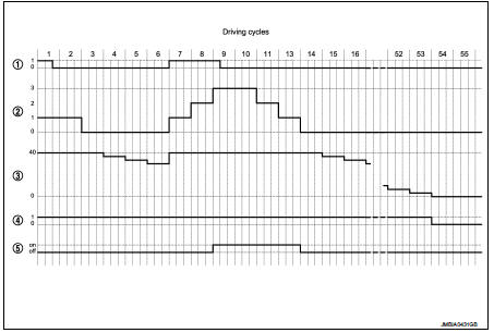
1. Present malfunction

1. Present malfunction 2. Driving cycle counter 3. Warm up cycle counter 4. Memorised malfunction 5. MI state

NOTE

: Driving cycle and warm up cycle are both detected in the same cycle.

Consult-III Function

FUNCTION
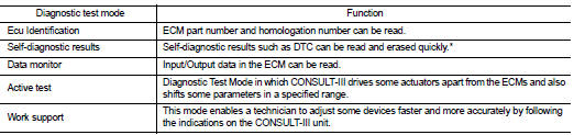
*: The following emission-related diagnostic information is cleared when the

*: The following emission-related diagnostic information is cleared when the ECM memory is erased.

• Diagnostic trouble codes

SELF-DIAGNOSTIC MODE

Self Diagnostic Item
Regarding items detected in ???SELF-DIAG RESULTS??? mode, refer to EC-855, "DTC Index".

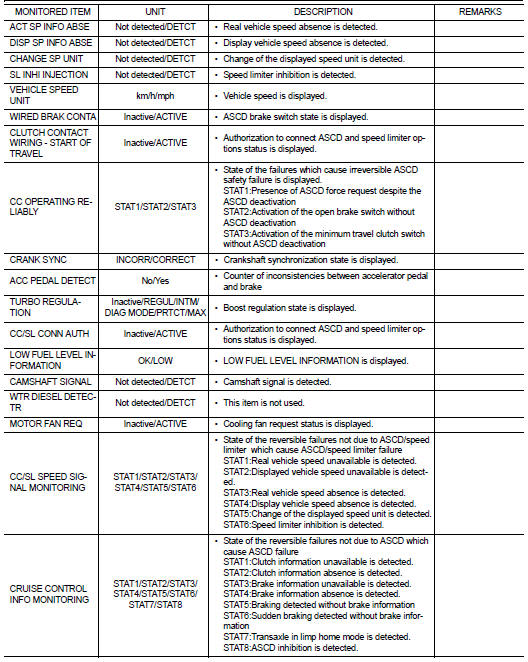
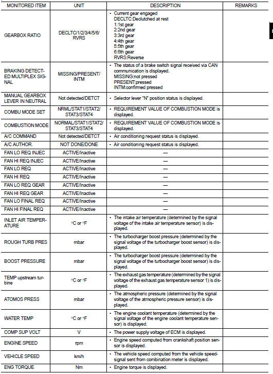
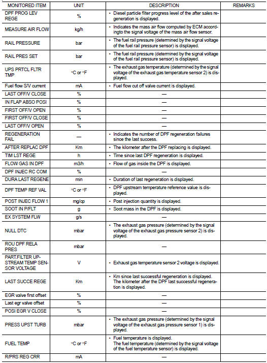
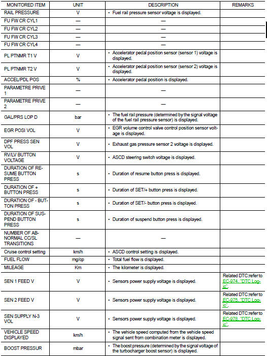
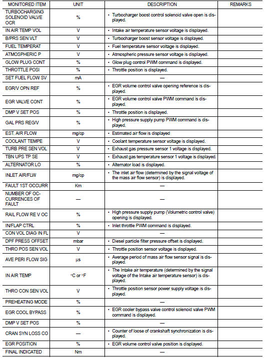
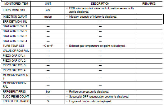
DATA MONITOR MODE
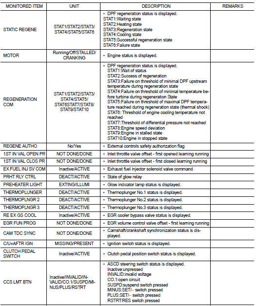


NOTE:

NOTE

:
Any monitored item that does not match the vehicle being diagnosed is deleted from the display automatically.

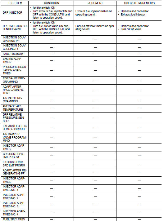
ACTIVE TEST MODE
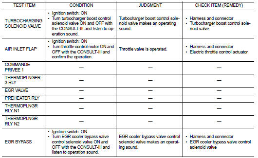


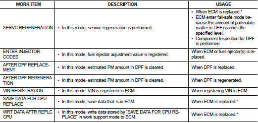
WORK SUPPORT MODE

WORK SUPPORT MODE

Work Item

*: The necessary operation is different depending on the operation result of

*: The necessary operation is different depending on the operation result of ECM data save or write. Always perform the operation according to procedures. Refer to EC-879, "Work Procedure".