LAN system can fundamental

Trouble diagnosis

In this manual: LAN system can fundamental
Foreword — 1General information — 45Engine Mechanical MR16DDT — 61Engine Mechanical HR16DE — 52Engine Mechanical K9K — 46Engine Lubrication System MR16DDT — 18Engine Lubrication System HR16DE — 14Engine Lubrication System K9K — 11Engine Cooling System MR16DDT — 28Engine Cooling System HR16DE — 29Engine Cooling System K9K — 24Engine Control System MR16DDT — 163Engine Control System HR16DE — 115Engine Control System K9K — 129Fuel System MR16DDT — 13Fuel system HR16DE — 11Fuel system K9K — 12Exhaust system MR16DDT — 7Exhaust system HR16DE — 10Exhaust system K9K — 7Starting system — 24Accelerator control system — 6Clutch — 25Driveline transfer: TY21B — 77Driveline rear propeller Shaft: 3Fφ16-ETJ75 — 12Driveline rear final drive: RTVS — 31Transaxle & transmission 5MT: RS5F92R — 31Transaxle & transmission 6MT: RS6F94R — 30Transaxle & transmission CVT: RE0F10B — 93Transaxle & transmissioN CVT: RE0F11A — 103Front Axle MR16DDT — 18Front Axle HR16DE — 17Front Axle K9K — 17Rear Axle 2WD — 6Rear Axle 4WD — 13Front Suspension — 21Rear Suspension 2WD — 13Rear Suspension 4WD — 17Road Wheels & Tires — 6Brake System LHD — 24Brake System RHD — 24Parking Brake System — 8Brake Control System without ESP — 44Brake Control System with ESP — 63Steering System — 14Steering Control System — 27Seat Belt — 8SRS Airbag — 24SRS Airbag Control System — 93Ventilation System — 11Heater & Air Conditioning System HR16DE — 28Heater & Air Conditioning System MR16DDT — 28Heater & Air Conditioning Control System Type 1 — 49Heater & Air Conditioning Control System Type 2 — 51Heater & Air Conditioning Control System Type 3 — 32Heater & Air Conditioning Control System Type 4 — 40Heater & Air Conditioning Control System Type 5 — 21Interior — 16Instrument Panel — 10Seat — 18Door & Lock Type 1 — 83Door & Lock type 2 — 80Door & Lock type 3 — 65Door & Lock type 4 — 60Security Control System with intelligent key system — 82Security Control System without intelligent key system — 41Glass & Window System — 15Power Window Control System — 28Body Repair — 13Exterior — 20Mirrors — 26Exterior Lighting System Halogen type — 51Interior Lighting System — 24Wiper & Washer — 45Defogger — 31Horn — 4Power Outlet — 4Body Control System With intelligent key system — 21Body Control System Without intelligent key system — 23LAN system can fundamental — 6LAN system can — 31LAN System can system (type 1) — 1LAN System can system (type 2) — 1LAN System can system (type 3) — 1LAN System can system (type 4) — 1LAN System can system (type 5) — 1LAN System can system (type 6) — 1LAN System can system (type 7) — 2LAN System can system (type 8) — 1LAN System can system (type 9) — 1LAN System can system (type 10) — 1LAN System can system (type 11) — 1Power Control System IPDM E/R (with I-key) — 14Power Control System IPDM E/R (without I-key) — 14Power Control System Power distribution system — 25Charging System — 22Power Supply, Ground & Circuit Elements — 20Meter, Warning Lamp & Indicator — 33Warning Chime System — 22Audio, Visual & Navigation System Audio without navigation — 30Audio, Visual & Navigation System Audio with navigation — 33Audio, Visual & Navigation System NISSAN dynamic control system — 22Cruise Control System — 1Drive Mode System — 10Maintenance — 14
~3min read

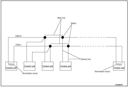
System Diagram


Condition of Error Detection

Condition of Error Detection

DTC (e.g. U1000 and U1001) of CAN communication is indicated on SELF-DIAG RESULTS on CONSULT-III if a CAN communication signal is not transmitted or received between units for 2 seconds or more.

CAN COMMUNICATION SYSTEM ERROR

• CAN communication line open (CAN-H, CAN-L, or both) • CAN communication line short (ground, between CAN communication lines, other harnesses)
• Error of CAN communication control circuit of the unit connected to CAN communication line

WHEN DTC OF CAN COMMUNICATION IS INDICATED EVEN THOUGH CAN COMMUNICATION SYSTEM IS NORMAL

• Removal/installation of parts: Error may be detected when removing and installing CAN communication unit and related parts while turning the ignition switch ON. (A DTC except for CAN communication may be detected.)
• Fuse blown out (removed): CAN communication of the unit may cease. • Voltage drop: Error may be detected if voltage drops due to discharged battery when turning the ignition switch ON (Depending on the control unit which carries out CAN communication). • Error may be detected if the power supply circuit of the control unit, which carries out CAN communication, malfunctions (Depending on the control unit which carries out CAN communication).

• Error may be detected if reprogramming is not completed normally.

CAUTION:
CAN communication system is normal if DTC of CAN communication is indicated on SELF-DIAG RESULTS of CONSULT-III under the above conditions. Erase the memory of the self-diagnosis of each unit.

Symptom When Error Occurs in CAN Communication System

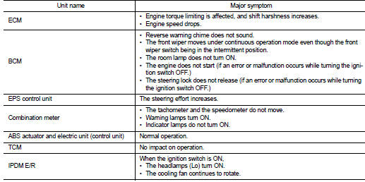
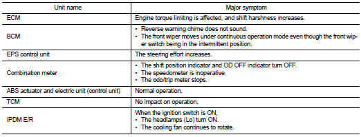
In CAN communication system, multiple units mutually transmit and receive signals. Each unit cannot transmit and receive signals if any error occurs on CAN communication line. Under this condition, multiple control units related to the root cause malfunction or go into fail-safe mode.

ERROR EXAMPLE

NOTE

:
Each vehicle differs in symptom of each unit under fail-safe mode and CAN communication line wiring.

Example: Main Line Between Data Link Connector and ABS Actuator and Electric Unit (Control Unit) Open Circuit
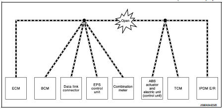
Example: TCM Branch Line Open Circuit
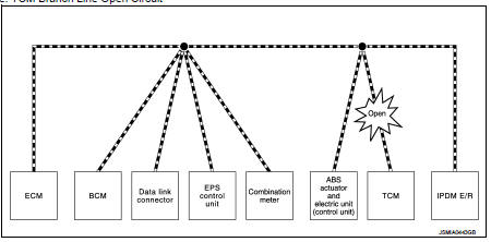
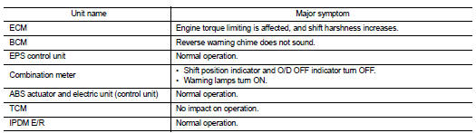
Example: TCM Branch Line Open Circuit


NOTE:

NOTE

:
The model (all units on CAN communication system are Diag on CAN) cannot perform CAN diagnosis with CONSULT-III if the following error occurs. The error is judged by the symptom.

Example: Data Link Connector Branch Line Open Circuit

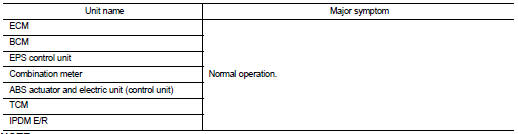
Example: Data Link Connector Branch Line Open Circuit


NOTE:

NOTE

:
When data link connector branch line is open, transmission and reception of CAN communication signals are not affected. Therefore, no symptoms occur. However, be sure to repair malfunctioning circuit.

Example: CAN-H, CAN-L Harness Short Circuit


Can diagnosis with consult-III

Can diagnosis with consult-III

CAN diagnosis on CONSULT-III extracts the root cause by receiving the following information.

• Response to the system call • Control unit diagnosis information • Self-diagnosis
• CAN diagnostic support monitor

Self-Diagnosis

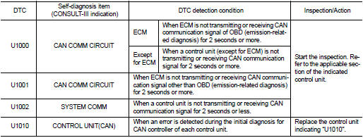
If communication signals cannot be transmitted or received among units communicating via CAN communication line, CAN communication-related DTC is displayed on the CONSULT-III “Self Diagnostic Result” screen.

NOTE

:
The following table shows examples of CAN communication-related DTC. For other DTC, refer to the applicable sections.
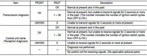
Can Diagnostic Support Monitor

Can Diagnostic Support Monitor

MONITOR ITEM (CONSULT-III)

Example: CAN DIAG SUPPORT MNTR indication

Without PAST

Without PAST


With PAST

With PAST

How to Use Can Communication Signal Chart

How to Use Can Communication Signal Chart

The CAN communication signal chart lists the signals needed for trouble diagnosis. It is useful for detecting the root cause by finding a signal related to the symptom, and by checking transmission and reception unit.

Basic inspection