Rear Suspension 4WD

Wheel alignment

In this manual: Rear Suspension 4WD
Foreword — 1General information — 45Engine Mechanical MR16DDT — 61Engine Mechanical HR16DE — 52Engine Mechanical K9K — 46Engine Lubrication System MR16DDT — 18Engine Lubrication System HR16DE — 14Engine Lubrication System K9K — 11Engine Cooling System MR16DDT — 28Engine Cooling System HR16DE — 29Engine Cooling System K9K — 24Engine Control System MR16DDT — 163Engine Control System HR16DE — 115Engine Control System K9K — 129Fuel System MR16DDT — 13Fuel system HR16DE — 11Fuel system K9K — 12Exhaust system MR16DDT — 7Exhaust system HR16DE — 10Exhaust system K9K — 7Starting system — 24Accelerator control system — 6Clutch — 25Driveline transfer: TY21B — 77Driveline rear propeller Shaft: 3Fφ16-ETJ75 — 12Driveline rear final drive: RTVS — 31Transaxle & transmission 5MT: RS5F92R — 31Transaxle & transmission 6MT: RS6F94R — 30Transaxle & transmission CVT: RE0F10B — 93Transaxle & transmissioN CVT: RE0F11A — 103Front Axle MR16DDT — 18Front Axle HR16DE — 17Front Axle K9K — 17Rear Axle 2WD — 6Rear Axle 4WD — 13Front Suspension — 21Rear Suspension 2WD — 13Rear Suspension 4WD — 17Road Wheels & Tires — 6Brake System LHD — 24Brake System RHD — 24Parking Brake System — 8Brake Control System without ESP — 44Brake Control System with ESP — 63Steering System — 14Steering Control System — 27Seat Belt — 8SRS Airbag — 24SRS Airbag Control System — 93Ventilation System — 11Heater & Air Conditioning System HR16DE — 28Heater & Air Conditioning System MR16DDT — 28Heater & Air Conditioning Control System Type 1 — 49Heater & Air Conditioning Control System Type 2 — 51Heater & Air Conditioning Control System Type 3 — 32Heater & Air Conditioning Control System Type 4 — 40Heater & Air Conditioning Control System Type 5 — 21Interior — 16Instrument Panel — 10Seat — 18Door & Lock Type 1 — 83Door & Lock type 2 — 80Door & Lock type 3 — 65Door & Lock type 4 — 60Security Control System with intelligent key system — 82Security Control System without intelligent key system — 41Glass & Window System — 15Power Window Control System — 28Body Repair — 13Exterior — 20Mirrors — 26Exterior Lighting System Halogen type — 51Interior Lighting System — 24Wiper & Washer — 45Defogger — 31Horn — 4Power Outlet — 4Body Control System With intelligent key system — 21Body Control System Without intelligent key system — 23LAN system can fundamental — 6LAN system can — 31LAN System can system (type 1) — 1LAN System can system (type 2) — 1LAN System can system (type 3) — 1LAN System can system (type 4) — 1LAN System can system (type 5) — 1LAN System can system (type 6) — 1LAN System can system (type 7) — 2LAN System can system (type 8) — 1LAN System can system (type 9) — 1LAN System can system (type 10) — 1LAN System can system (type 11) — 1Power Control System IPDM E/R (with I-key) — 14Power Control System IPDM E/R (without I-key) — 14Power Control System Power distribution system — 25Charging System — 22Power Supply, Ground & Circuit Elements — 20Meter, Warning Lamp & Indicator — 33Warning Chime System — 22Audio, Visual & Navigation System Audio without navigation — 30Audio, Visual & Navigation System Audio with navigation — 33Audio, Visual & Navigation System NISSAN dynamic control system — 22Cruise Control System — 1Drive Mode System — 10Maintenance — 14
~3min read
Inspection

DESCRIPTION

Measure wheel alignment under unladen conditions.

NOTE

:
“Unladen conditions” means that fuel, engine coolant, and lubricant are full. Spare tire, jack, hand tools and mats are in designated positions.

PRELIMINARY CHECK

Check the following:
• Tires for improper air pressure and wear • Road wheels for runout: refer to WT-7, "Inspection". • Wheel bearing axial end play: refer to RAX-12, "Inspection".

• Shock absorber operation • Each mounting point of axle and suspension for looseness and deformation • Each of lower link, upper link, rear suspension member, suspension arm and shock absorber for cracks, deformation, and other damage • Vehicle height (posture)

CAMBER

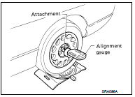
• Measure camber of both right and left wheels with a suitable alignment gauge.

Camber : Refer to RSU-37, "Wheel Alignment".

• If camber is outside specified range, adjust with adjusting bolt in rear lower link. Refer to RSU-21, "Adjustment".
TOE-IN

TOE-IN

Measure toe-in by the following procedure.

WARNING:
• Always perform the following procedure on a flat surface.

• Check that no person is in front of vehicle before pushing it.

1. Bounce the front of vehicle up and down to stabilize the vehicle height (posture). 2. Push vehicle straight ahead about 5 m (16 ft).

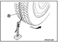
3. Put matching mark (A) on base line of the tread (rear side) of both tires at the same height of hub center. These are measuring points.
4. Measure distance (A) (rear side).

4. Measure distance (A) (rear side).

: Vehicle front

5. Push vehicle slowly ahead to rotate wheels 180 degrees (1/2 turn).

NOTE

:
If the wheels rotates more than 180 degrees (1/2 turn), start this procedure again from the beginning. Do not push the vehicle backward.

6. Measure distance (B) (front side).

Total toe-in = A − B Total toe-in : Refer to RSU-37, "Wheel Alignment".

• If toe-in is outside specified range, adjust with adjusting bolt in upper link and lower link. Refer to RSU- 21, "Adjustment".

Adjustment

Adjustment

CAMBER, TOE-IN

CAUTION:
• Adjust camber first, then adjust toe-in last. never change the order. • If camber angle needs to be adjusted, toe-in adjustment is necessary.

• Minimize difference of left and right toe-in within tolerance

.

1. Loosen mounting nuts of upper link and lower link on the suspension member side.

2. Adjust camber and toe-in by turning upper link adjusting bolt (1) and lower link adjusting bolt (2) alternately.

A : Left side
B : Right side

NOTE: Upper link adjusting bolt Positive direction : Upper link slides into inner side of vehicle.
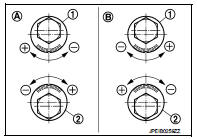
Negative direction : Upper link slides into outer side of vehicle.

Lower link adjusting bolt Positive direction : Lower link slides into outer side of vehicle.

Negative direction : Lower link slides into inner side of vehicle.

• Refer to the table below for easier adjustment
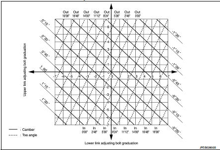
• Refer to the table below for easier adjustment

- Obtain the amount of camber and toe-in by calculating the difference

- Obtain the amount of camber and toe-in by calculating the difference between the measurement result and the standard value.

- Obtain the needed adjustment amount from the graph and move adjusting bolts, respectively.

3. After adjustment, tighten mounting nuts of upper link and lower link on the suspension member side.

CAUTION:
When tightening nut to the specified torque, the bolt must be fixed with a wrench.