Abs Actuator and Electric Unit (control Unit)
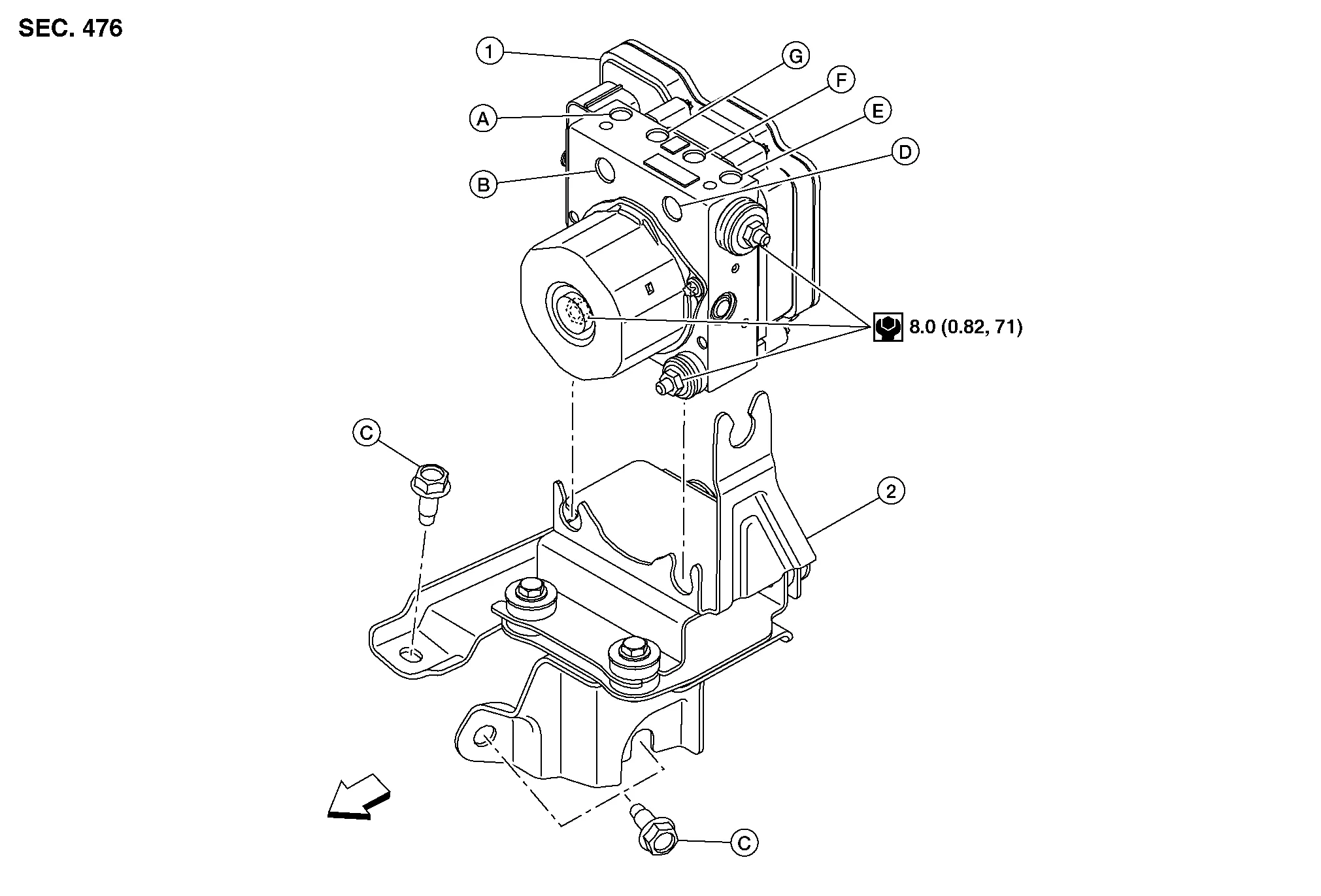
| 1. | ABS actuator and electric unit (control unit) | 2. | Bracket | A. | To rear (RH) brake caliper. Refer to Exploded View. |
| B. | From master cylinder secondary side. Refer to Exploded View. | C. | Refer to Removal and Installation. | D. | From master cylinder primary side. Refer to Exploded View. |
| E. | To rear (LH) brake caliper. Refer to Exploded View. | F. | To front (RH) brake caliper. Refer to Exploded View. | G. | To front (LH) brake caliper. Refer to Exploded View. |
 |
Front |
REMOVAL
Disconnect negative battery terminal. Refer to Exploded View.
Remove cowl top cover. Refer to Removal and Installation - Cowl Top Cover.
Remove cowl top extension. Refer to Removal and Installation - Cowl Top Extension.
Separate brake tubes from ABS actuator and electric unit (control unit). Refer to Exploded View.
Disconnect harness connector from ABS actuator and electric unit (control unit).
Loosen ABS actuator and electric unit (control unit) grommet nuts. Refer to Exploded View.
Remove ABS actuator and electric unit (control unit) from bracket.
If necessary, remove bolts and bracket.
INSTALLATION
Installation is in the reverse order of removal.
For tapered bolt (A), tighten bolt to specification.

Tightening torque : 26 N·m Except for tapered bolt (A), tighten bolt to specification.
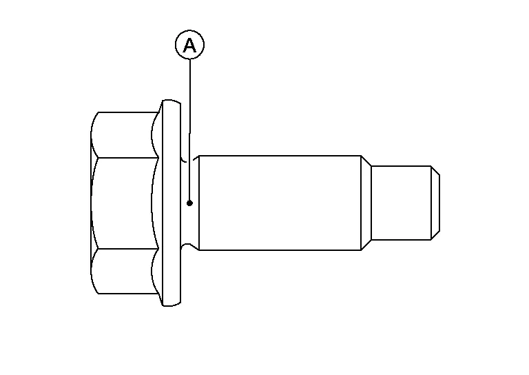
Tightening torque : 25 N·m After work is completed, bleed air from brake tube. Refer to Bleeding Brake System.
Adjust the neutral position of steering angle sensor. Refer to Description.
Perform calibration of the decel G sensor. Refer to Description.