Component Parts. Brake Control System
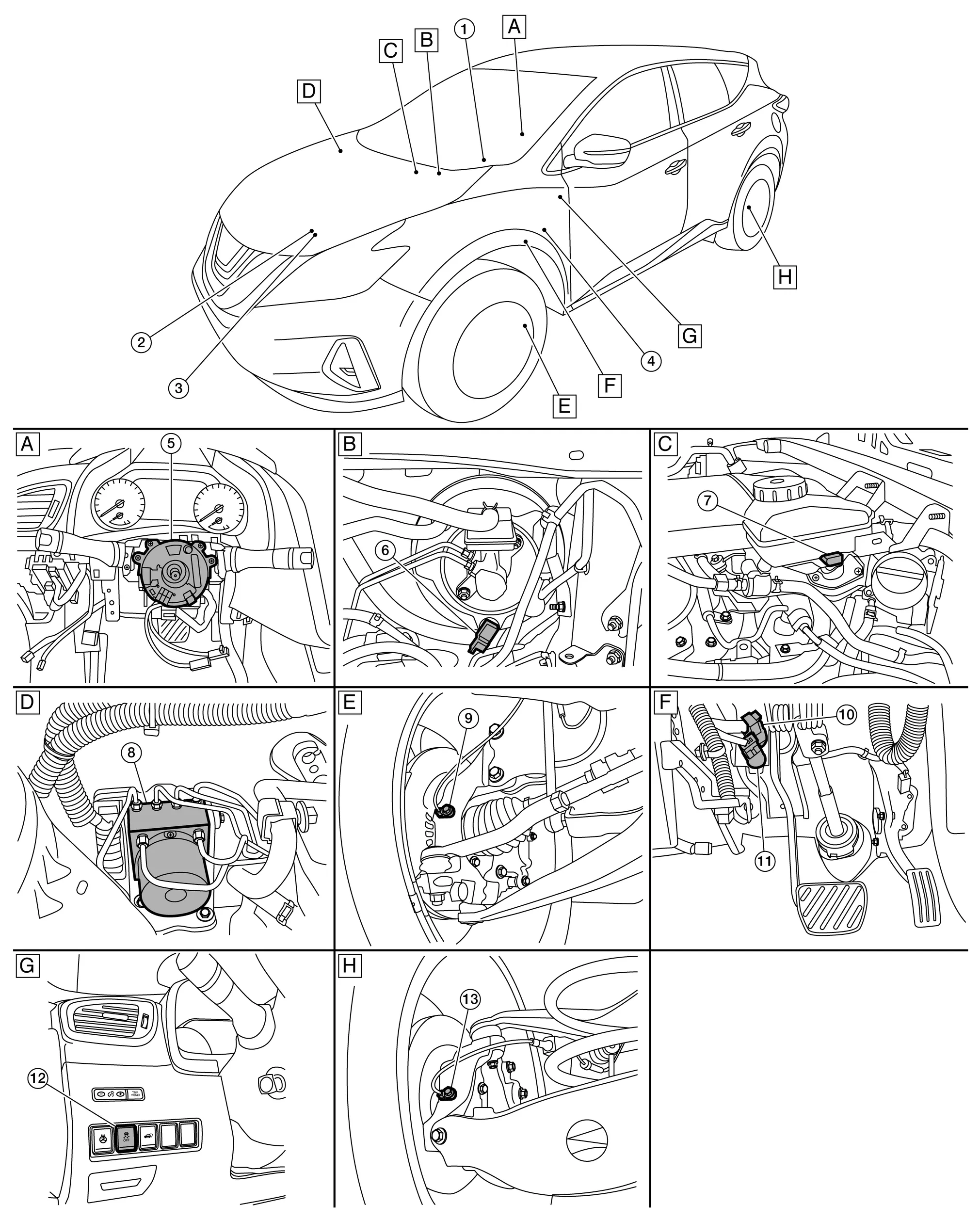
| A. | Steering column (view with steering wheel removed) |
B. | Engine room (LH) | C. | Engine room (LH) |
| D. | Engine room (RH) | E. | Left front wheel area | F. | Brake pedal area |
| G. | Left side of instrument panel | H. | Left rear wheel area |
| No. | Component | Function |
|---|---|---|
| 1. | Combination meter |
|
| 2. | TCM (Transmission Control Module) | TCM transmits the signal related to CVT control to ADAS control unit via CAN communication. Refer to Component Parts Location for detailed component location. |
| 3. | ECM (Engine Control Module) | ECM transmits the accelerator pedal position signal via CAN communication. Refer to Component Parts Location for detailed component location. |
| 4. | Driver assistance buzzer | Refer to Driver Assistance Buzzer. |
| 5. | Steering angle sensor | Refer to Steering Angle Sensor. |
| 6. | Vacuum sensor | Refer to Vacuum Sensor. |
| 7. | Brake fluid level switch | Refer to Brake Fluid Level Switch. |
| 8. | ABS (Anti-lock Braking System) actuator and electric unit (control unit) |
|
| 9. | Front wheel sensor LH (RH similar) | Refer to Wheel Sensor and Sensor Rotor. |
| 10. | Brake pedal position switch | Refer to Brake Pedal Position Switch / Stop Lamp Switch. |
| 11. | Stop lamp switch | |
| 12. | VDC (Nissan Murano Vehicle Dynamic Control) off switch | Refer to VDC OFF Switch. |
| 13. | Rear wheel sensor LH (RH similar) | Refer to Wheel Sensor and Sensor Rotor. |
The ABS actuator and electric unit (control unit) is located the right side of the engine room.
Electric unit (control unit) is integrated with actuator and comprehensively controls VDC function, TCS function, ABS function, EBD function, brake assist function and hill start assist function.
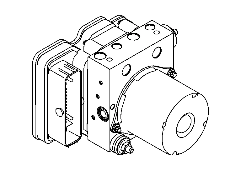
ELECTRIC UNIT (CONTROL UNIT)
Brake fluid pressure, engine and transmission are controlled according to signals from each sensor.
If malfunction is detected, the system enters fail-safe mode.
ACTUATOR
The following components are integrated with ABS actuator:
Pump
Returns the brake fluid reserved in reservoir to master cylinder by reducing pressure.
Motor
Activates the pump according to signals from ABS actuator and electric unit (control unit).
Motor Relay
Operates the motor ON/OFF according to signals from ABS actuator and electric unit (control unit).
Actuator Relay
Operates each valve ON/OFF according to signals from ABS actuator and electric unit (control unit).
ABS IN Valve and ABS OUT Valve
Increases, holds or decreases the fluid pressure of each caliper according to signals from ABS actuator and electric unit (control unit).
Pressure Sensor
Detects the brake fluid pressure and transmits signal to ABS actuator and electric unit (control unit).
Cut Valve 1 (Primary Line), Cut Valve 2 (Secondary Line)
Shuts off the ordinary brake line from master cylinder when VDC function, TCS function, brake assist function, hill start assist function are activated.
Yaw Rate/Side/Decel G Sensor
Calculates the following information that affects the vehicle and transmits a signal to ABS actuator and electric unit (control unit). [Yaw rate/side/decel G sensor is integrated into the ABS actuator and electric unit (control unit).]
Vehicle rotation angular velocity (yaw rate signal)
Vehicle lateral acceleration (side G signal)
Nissan Murano Vehicle longitudinal acceleration (decel G signal)
Power supply is supplied to detection portion so that magnetic field line is read. Magnetic field that is detected is converted to current signal.
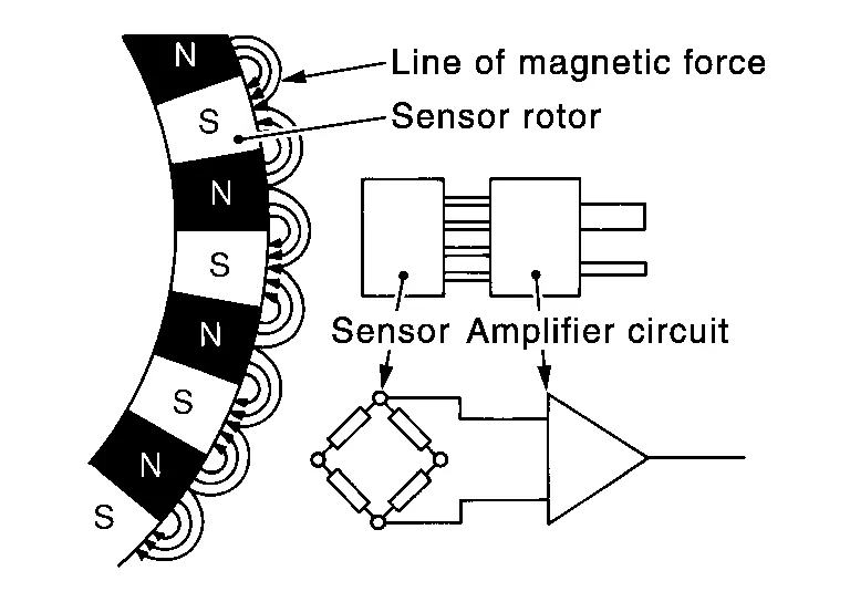
When sensor rotor rotates, magnetic field changes. Magnetic field change is converted to current signals (rectangular wave) and is transmitted to ABS actuator and electric unit (control unit). Change of magnetic field is proportional to wheel speed.
The steering angle sensor is located behind the steering wheel.
Detects the following information and transmits steering angle signal to ABS actuator and electric unit (control unit) via CAN communication:
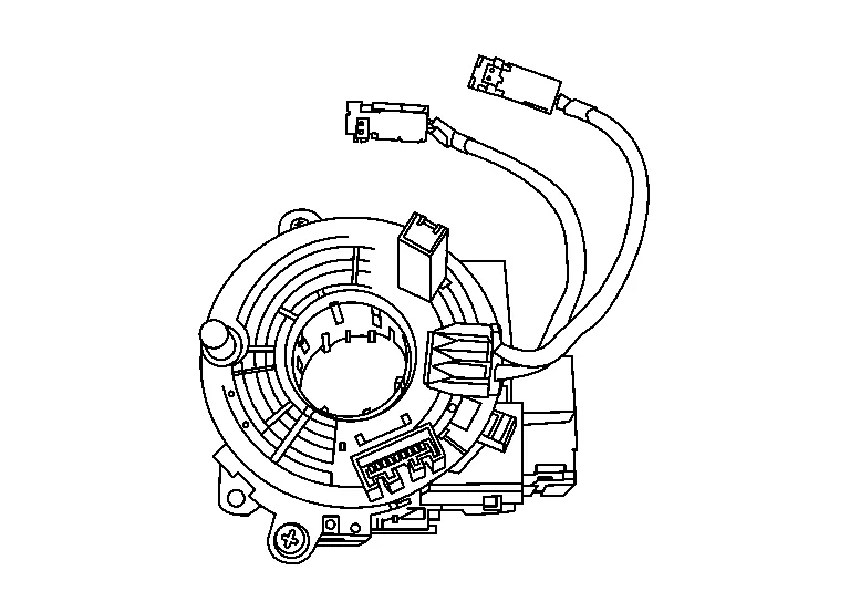
Steering angle sensor malfunction signal
Steering wheel rotation amount
Steering wheel rotation angular velocity
Steering wheel rotation direction
The brake fluid level switch is located on the left side of the master cylinder reservoir.
Detects the brake fluid level in reservoir tank and transmits converted electric signal from combination meter to ABS actuator and electric unit (control unit) via CAN communication when brake fluid level is the specified level or less.
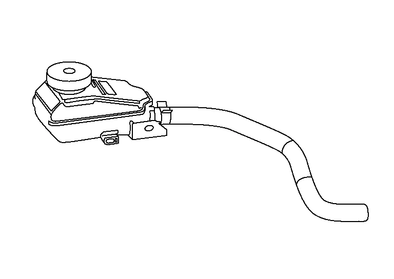
The vacuum sensor is located on the left side of the master cylinder reservoir.
Detects the vacuum in brake booster and transmits converted electric signal to ABS actuator and electric unit (control unit).

Detects the operation status of parking brake switch and transmits converted electric signal from combination meter to ABS actuator and electric unit (control unit).
This is an integrated switch with switches for other functions.
Non-operational status or standby status of the following functions can be selected using VDC OFF switch. VDC OFF indicator lamp indicates the operation status of function (ON: Non-operational status, OFF: Standby status).

Nissan Murano Vehicle Dynamic Control function
Traction Control System function
Automatic Emergency Braking function
VDC OFF indicator lamp turns OFF (standby status) when the engine is started again after it is stopped once while VDC OFF indicator lamp is ON (non-operational status).
ADAS control unit is at the front of center console.
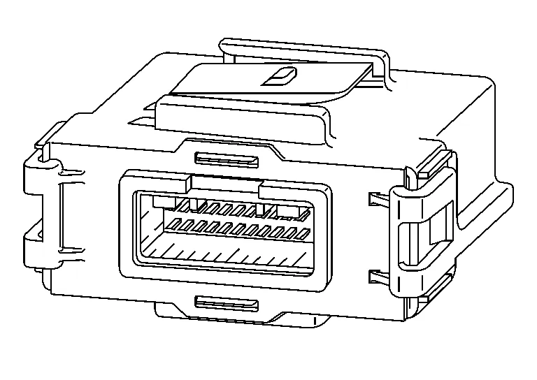
Communicates with each control unit via CAN communication/ITS communication.
ADAS control unit included gateway function, and necessary for system control signals are transmitted to each control unit between CAN communication and ITS communication by the ADAS control unit.
ADAS control unit controls the each system, based on ITS communication signal and CAN communication signal from each control unit.
Distance sensor is installed on the front of the vehicle and detects a vehicle ahead by using millimeter waves.
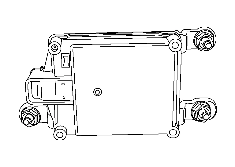
Distance sensor detects radar reflected from a Nissan Murano vehicle ahead by irradiating radar forward and calculates a distance from the vehicle ahead and relative speed, based on the detected signal.
Distance sensor transmits information from the Nissan Murano vehicle to ADAS control unit via ITS communication.
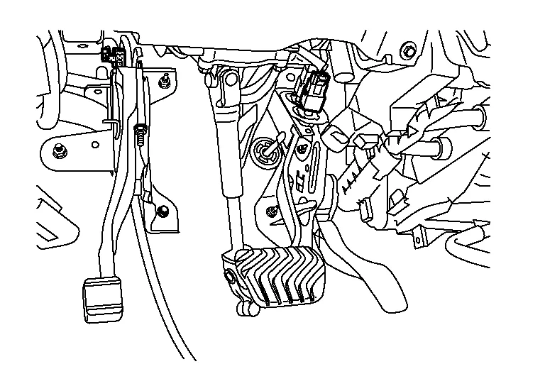
Brake pedal position switch is installed at the upper part of the brake pedal and detects a brake operation performed by the driver.

Brake pedal position switch is turned OFF when depressing the brake pedal.
Brake pedal position switch signal is input to ECM. Brake pedal position switch signal is transmitted from ECM to ADAS control unit via CAN communication.
Stop lamp switch is installed at the lower part of the brake pedal and detects a brake operation performed by the driver.
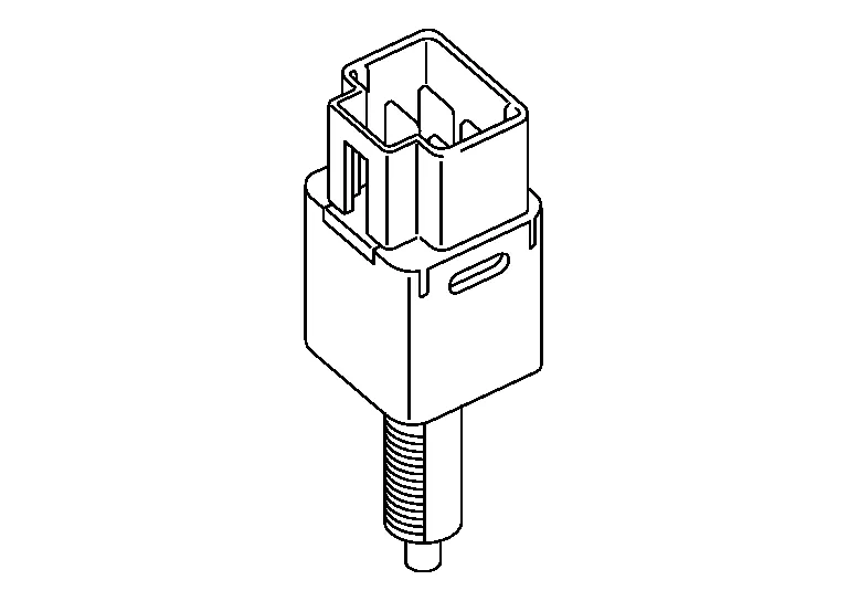
Stop lamp switch is turned ON, when depressing the brake pedal.
Stop lamp switch signal is input to ECM and ABS actuator and electric unit (control unit). Stop lamp switch signals are transmitted from ECM and ABS actuator and electric unit (control unit) to ADAS control unit via CAN communication.
ICC brake hold relay is installed in the engine room (left side).
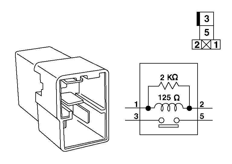
When the brake is activated by the system, the ICC brake hold relay turns ON the stop lamp by bypassing the circuit of the stop lamp, according to a signal transmitted from the ADAS control unit.
Driver assistance buzzer is installed behind the finisher to the left of the left knee airbag module.
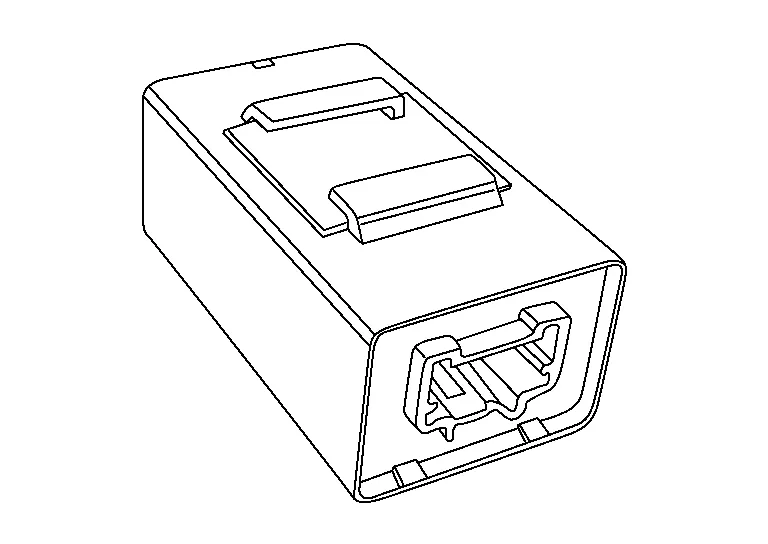
When a driver assistance buzzer signal is received from the ADAS control module, the driver assistance buzzer sounds a buzzer.