Engine Mechanical :: Preparation. Preparation
Tool number (TechMate No.) Tool name | Description | |
|---|---|---|
— (J-43897-18) Oxygen sensor thread cleaner |
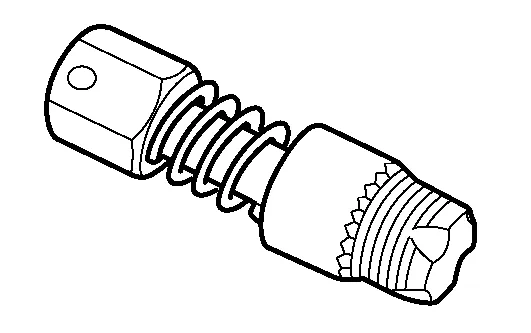 |
Reconditioning the exhaust system threads before installing a new oxygen sensor (Use with anti-seize lubricant shown below.) J-43897-18 (18 mm dia.) for zirconia oxygen sensor |
— (J-50288) Ring gear stopper |
 |
Removing and installing crankshaft pulley |
16441 6N210 (J-45488) Quick connector release |
 |
Removing fuel tube quick connectors in engine room (Available in SEC. 164 of PARTS CATALOG: Part No. 16441 6N210) |
— (J-48891) Spark plug socket |
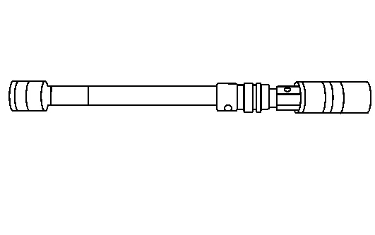 |
Removing and installing spark plug |
KV10111100 (J-37228) Seal cutter |
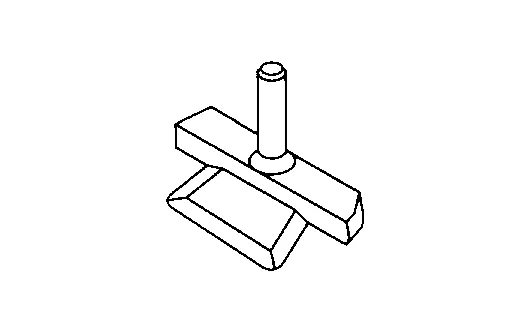 |
Removing oil pan and timing chain case |
KV991J0050 (J-44626) Air fuel sensor Socket |
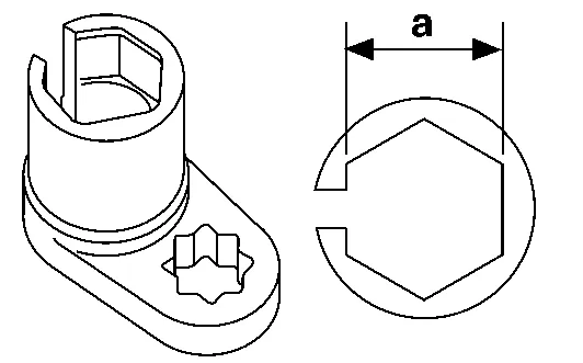 |
Loosening or tightening air fuel ratio A/F sensor a: 22 mm (0.87 in) |
KV10114400 (J-38365) Heated oxygen sensor wrench |
 |
Loosening or tightening rear heated oxygen sensor a: 22 mm (0.87 in) |
— (J-37066) Seal installer |
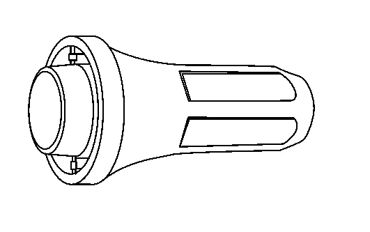 |
Installing front main seal |
— (J-47128) Seal installer |
 |
Installing rear main seal |
KV10112100 (BT-8653-A) Torque angle meter |
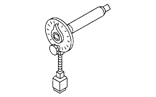 |
Tightening bolts for bearing cap, cylinder head, etc. |
Tool number (TechMate No.) Tool name | Description | |
|---|---|---|
KV10116200 (J-26336-A) Valve spring compressor 1. KV10115900 (J-26336-20) Attachment 2. KV10109220 ( — ) Adapter |
 |
Disassembling valve mechanism Part (1) is a component of KV10116200 (J-26336-A), but part (2) is not. |
— ( — ) Manual lift table caddy |
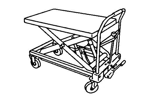 |
Removing and installing engine |
ST16610001 (J-23907) Pilot converter puller |
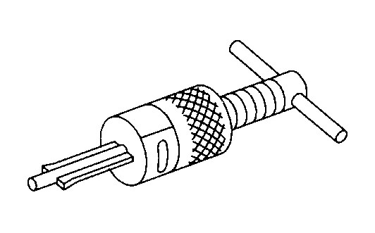 |
Removing crankshaft pilot converter |
— ( — ) Tube presser |
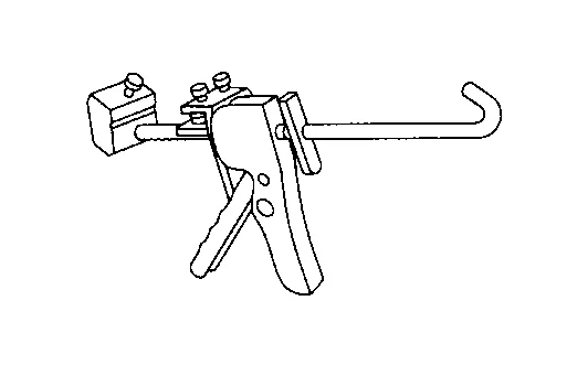 |
Pressing the tube of liquid gasket |
— ( — ) Piston ring compressor |
 |
Installing piston assembly into cylinder bore |
— ( — ) Pulley holder |
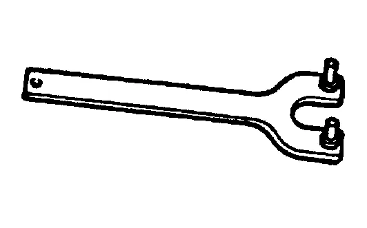 |
Removing and installing Crankshaft pulley (Holding Crankshaft pulley) |
— ( — ) Pulley puller |
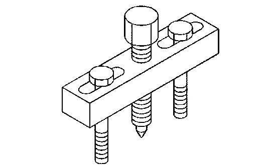 |
Removing crankshaft pulley |
— ( — ) Valve seat cutter set |
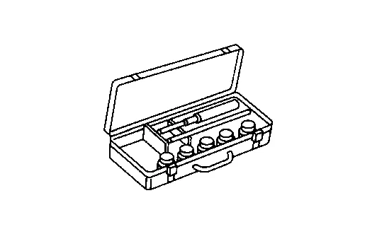 |
Finishing valve seat dimensions |
— ( — ) Piston ring expander |
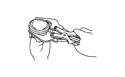 |
Removing and installing piston ring |
— (J-39386) Valve oil seal drift |
 |
Installing valve oil seal |
— ( — ) Valve guide drift |
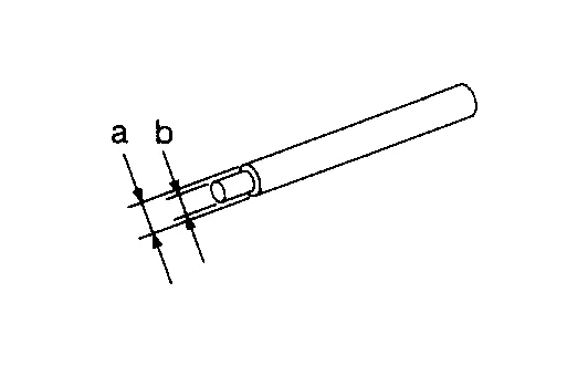 |
Removing and installing valve guide Intake & Exhaust:a: 9.5 mm (0.374 in) dia.b: 5.5 mm (0.217 in) dia. |
— ( — ) Valve guide reamer |
 |
1: Reaming valve guide inner hole 2: Reaming hole for oversize valve guide Intake & Exhaust:d1: 6.0 mm (0.236 in) dia.d2: 10.2 mm (0.402 in) dia. |
— ( — ) Anti-seize lubricant (Permatex 133AR or equivalent meeting MIL specification MIL-A-907) |
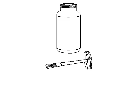 |
Lubricating oxygen sensor thread cleaning tool when reconditioning exhaust system threads |
KV10115600 (J-38958) Valve oil seal drift |
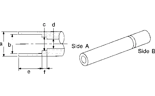 |
Installing valve oil seal Use side A.a: 20 (0.79) dia. d: 8 (0.31) dia.b: 13 (0.51) dia. e: 10.7 (0.421) dia.c: 10.3 (0.406) dia. f: 5 (0.20) dia.Unit: mm (in) |
— ( — ) Power tool |
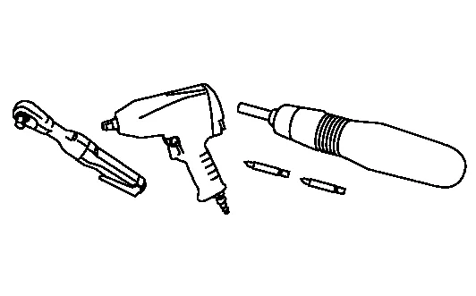 |
Loosening nuts, screws, and bolts |
KV10107902 (J-38959) Valve oil seal puller with adapter (1) |
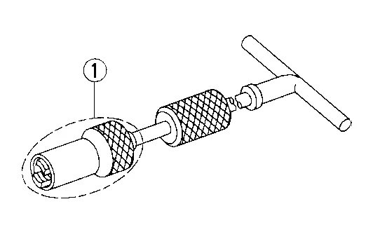 |
Removing valve oil seal |
ST0501S000 Engine stand assembly ( — ) 1. ST05011000 ( — ) Engine stand 2. ST05012000 ( — ) Base |
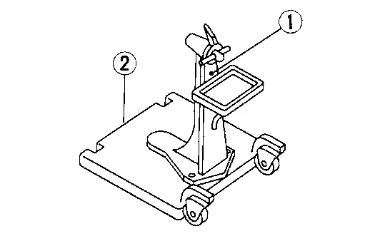 |
Disassembling and assembling |
KV10106500 ( — ) Engine stand shaft |
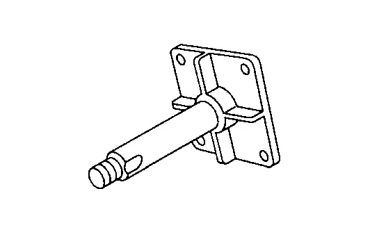 |
Engine supporting |
KV10115300 ( — ) Engine sub-attachment |
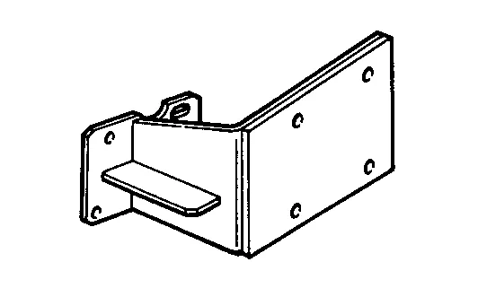 |
Disassembling and assembling |
— (J-45816) E20 Socket |
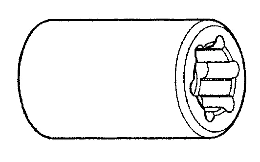 |
Removing and installing CVT drive plate bolts |