Front Camera Unit
VALUE ON THE DIAGNOSIS TOOL
| Monitor item | Condition | Value/Status | |
|---|---|---|---|
| CAMERA HIGH TEMP | When the temperature around lane camera unit is adequate | NORMAL | |
| When the temperate around the lane camera unit is high | HIGH | ||
| WIPER | Ignition switch ON | Wiper position is High | Hi |
| Wiper position is Low | Lo | ||
| Wiper position is OFF | Off | ||
| TURN SIGNAL | Turn signal lamp LH and RH blinking | LH&RH | |
| Turn signal lamp LH blinking | LH | ||
| Turn signal lamp RH blinking | RH | ||
| Turn signal lamps OFF | Off | ||
| Nissan Murano Vehicle SPEED | While drive | km/h | |
| DRIVER ASSIST SYSTEM SET | NO REQ | ||
| BRAKE OPERATION STATUS | When brake pedal is depressed | Off | |
| When brake pedal is depressed | On | ||
| When brake pedal is securely depressed | CNFRM | ||
| When brake pedal operation is not judged | UNKWN | ||
| AIMING DONE | Camera aiming is completed | finished | |
| Camera aiming is not adjusted | not finished | ||
| AIMING RESULT | Camera aiming is completed | OK | |
| Camera aiming is not completed | NOK | ||
| STEERING ANGLE | When driving straight | Approx. 0.0 deg | |
| When steering wheel is steered | Value of steering angle (deg) | ||
| YAW RATE | Nissan Murano Vehicle stopped | Approx. 0 deg/s | |
| Turning right | Negative value | ||
| Turning left | Positive value | ||
| FCTRY AIM YAW | Camera aiming is completed | 0 ± 3.0 deg | |
| FCTRY AIM ROL | Camera aiming is completed | 0 ± 3.0 deg | |
| FCTRY AIM PIT | Camera aiming is completed | 0 ± 3.0 deg | |
| LDW FUNCTION | When LDW function is ON | NORMAL | |
| When LDW function malfunction is detected | MALF | ||
| LDW SETTING DISPLAY | NTHNG | ||
| DRIVER ASSIST SYSTEM BZZR | NO REQ | ||
| LDW LEFT | Left side lane maker is not detected | Off | |
| Left side lane maker is detected | On | ||
| LDW RIGHT | Right side lane maker is not detected | Off | |
| Right side lane maker is detected | On | ||
| LDW STATUS DISPLAY | Off | ||
| HBA FUNCTION | — | ||
| DISTANCE | Drive the Nissan Murano vehicle and AEB system ON | When the lane camera detects an object to be controlled | Displays distance from Nissan Murano vehicle ahead |
| When the lane camera does not detect an object to be controlled | 0.0 m | ||
| RELATIVE SPEED | Drive the Nissan Murano vehicle and AEB system ON | When the lane camera detects an object to be controlled | Displays relative velocity |
| When the lane camera does not detect an object to be controlled | 0.0 m/s | ||
| Initialization ECU | Power switch ON | When initialization of the lane camera unit is not completed | INCOMP |
| When initialization of the lane camera unit is completed | COMP | ||
| HBA REQUEST | — | ||
| LOW BEAM STATUS | — | ||
| HIGH BEAM STATUS | — | ||
| NO-ENTRY SIGN DISPLAY | — | ||
TERMINAL LAYOUT
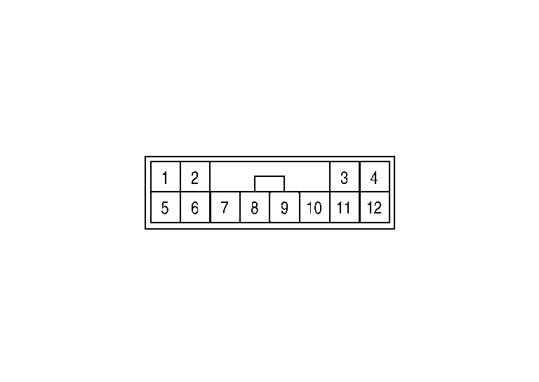
PHYSICAL VALUES
Terminal No. (Wire color) | Description | Condition | Value (Approx.) | ||
|---|---|---|---|---|---|
| + | – | Signal name | Input/Output | ||
1 (B) |
Ground | Ground | Output | — | 0 V |
3 (BG) |
Ignition power supply | Input | Ignition switch ON | Battery voltage | |
5 (L) |
ITS communication high | — | — | — | |
6 (Y) |
ITS communication low | — | — | — | |
Refer to Fail-safe (Lane Camera Unit).
If multiple DTCs are detected simultaneously, check them one by one depending on the following DTC inspection priority chart.
U1000-01: CAN COMM CIRCUIT [ELECTRICAL MALFUNCTION]
U1010-49: CONTROL UNIT (CAN) [INTERNAL ELECTRONIC ERROR]
U1321-55: CONFIG UNFINISHED [NOT CONFIGURED]
U1322-01: CONFIG WRITE ERROR [ELECTRICAL MALFUNCTION]
C1B00-4B: CAMERA UNIT MALF [OVER TEMPERATURE]
C1B01-54: CAM AIMING INCMP [MISSING CALIBRATION]
C1B09-17: POWER SUPPLY CIRCUIT [CIRC VOLT ABOVE THRESHOLD]
C1B0A-16: POWER SUPPLY CIRCUIT [CIRC VOLT BELOW THRESHOLD]
U0104-00: ADAS CAN CIRC 1
U0122-00: VDC CAN CIR 1 (LDP)
U0126-00: STRG SEN CAN CIR 1
U0405-83: ADAS CAN CIRC 2 [PROTECT CALCULATION ERROR]
U0428-83: STRG SEN CAN CIR2 [PROTECT CALCULATION ERROR]
C1B00-04: CAMERA UNIT MALF [SYSTEM INTERNAL MALFUNCTION]
C1B00-41: CAMERA UNIT MALF
C1B00-44: CAMERA UNIT MALF
C1B00-45: CAMERA UNIT MALF
C1B00-46: CAMERA UNIT MALF
C1B00-47: CAMERA UNIT MALF
C1B00-48: CAMERA UNIT MALF
C1B00-49: CAMERA UNIT MALF [INTERNAL ELECTRONIC ERROR]
C1B00-52: CAMERA UNIT MALF
C1B00-56: CAMERA UNIT MALF
C1B00-57: CAMERA UNIT MALF
C1B00-87: CAMERA UNIT MALF [MISSING MESSAGE]
×: Applicable
| DTC | Warning display | Fail-safe | |||||
|---|---|---|---|---|---|---|---|
| LDW system warning | I-LI system warning | LDW | I-LI | TSR | Reference | ||
| C1B00-4B | CAMERA UNIT MALF | ON | ON | × | × | × | DTC Description |
| C1B00-04 | CAMERA UNIT MALF | ON | ON | × | × | × | DTC Description |
| C1B00-41 | CAMERA UNIT MALF | ON | ON | × | × | × | DTC Description |
| C1B00-44 | CAMERA UNIT MALF | ON | ON | × | × | × | DTC Description |
| C1B00-45 | CAMERA UNIT MALF | ON | ON | × | × | × | DTC Description |
| C1B00-46 | CAMERA UNIT MALF | ON | ON | × | × | × | DTC Description |
| C1B00-47 | CAMERA UNIT MALF | ON | ON | × | × | × | DTC Description |
| C1B00-48 | CAMERA UNIT MALF | ON | ON | × | × | × | DTC Description |
| C1B00-49 | CAMERA UNIT MALF | ON | ON | × | × | × | DTC Description |
| C1B00-52 | CAMERA UNIT MALF | ON | ON | × | × | × | DTC Description |
| C1B00-56 | CAMERA UNIT MALF | ON | ON | × | × | × | DTC Description |
| C1B00-57 | CAMERA UNIT MALF | ON | ON | × | × | × | DTC Description |
| C1B00-87 | CAMERA UNIT MALF | ON | ON | × | × | × | DTC Description |
| C1B01-54 | CAMERA AIMING INCMP | ON | ON | × | × | × | DTC Description |
| C1B09-17 | POWER SUPPLY CIRC | ON | ON | × | × | × | DTC Description |
| C1B0A-16 | POWER SUPPLY CIRC 2 | ON | ON | × | × | × | DTC Description |
| U1000-01 | CAN COMM CIRCUIT | ON | ON | × | × | × | DTC Description |
| U1010-49 | CONTROL UNIT (CAN) | ON | ON | × | × | × | DTC Description |
| U0104-00 | ADAS CAN CIRC | ON | ON | × | × | — | DTC Description |
| U0122-00 | VDC CAN CIRC1 (LDP) | ON | ON | × | × | × | DTC Description |
| U0126–00 | STRG SEN CAN CIR1 | ON | ON | × | × | × | DTC Description |
| U0405-83 | ADAS CAN CIR 2 | ON | ON | × | × | — | DTC Description |
| U0428–83 | STRG SEN CAN CIR2 | ON | ON | × | × | — | DTC Description |
| U1321-55 | CONFIGURATION DATA ERROR | ON | ON | × | × | — | DTC Description |
| U1322-01 | CONFIG WRITE ERROR | ON | ON | × | × | — | DTC Description |