System. Hydraulic Pump Electric Power Steering System
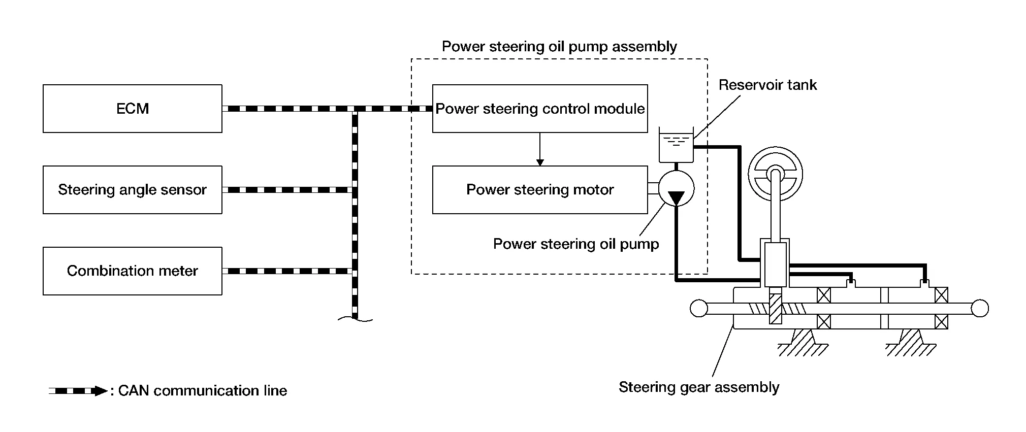
The system is composed primarily of the power steering oil pump assembly (power steering control module, power steering motor, power steering oil pump, and reservoir tank), hydraulic pipes, and steering gear assembly.
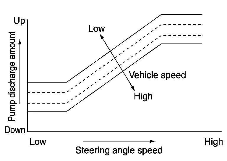
The power steering control module controls the speed of the power steering motor according to the Nissan Murano vehicle speed and steering angle speed. By changing the power steering oil pump flow, the power steering control module controls the steering assist force.
According to the power steering motor control, the system hydraulic pressure is transmitted from the power steering motor to power steering oil pump. The power steering oil pump is driven by the system hydraulic pressure.
After engine start, the hydraulic pump electric power steering system performs control.
When a malfunction occurs in the system, the fail-safe function stops the hydraulic pump electric power steering system (manual steering state) or restricts its operation (certain steering assist force). Refer to Fail-safe.
When the power steering function is used continuously in an extreme manner, the protective function reduces the output to the power steering motor. Refer to Protection Function.
SYSTEM DIAGRAM
INPUT SIGNAL AND OUTPUT SIGNAL
Communicates the signal from each control unit via CAN communication.
| Control unit | Signal status |
|---|---|
| ECM | Transmits mainly the following signal to power steering control module via CAN communication:
|
| Steering angle sensor | Transmits mainly the following signal to power steering control module via CAN communication:
|
| Combination meter | Transmits mainly the following signal to power steering control module via CAN communication:
Receives mainly the following signal from power steering control module via CAN communication:
|
OPERATION CHARACTERISTICS
When the steering angle speed is high or the vehicle speed is low, force is generated by increasing discharge amount from the power steering oil pump and by raising system hydraulic pressure.
OPERATION PRINCIPLE
When Steering Wheel is in the Neutral Position
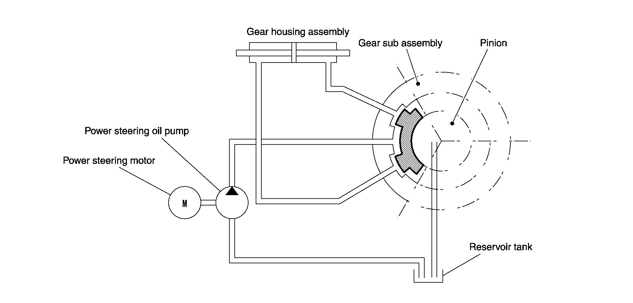
Because the hydraulic routes open at the power steering pump, gear housing right side, gear housing left side, and reservoir tank, the hydraulic pressure applied to the right side and left side of the gear housing is equal and no steering assist force is generated.
When Steering Wheel is Rotated to the Right
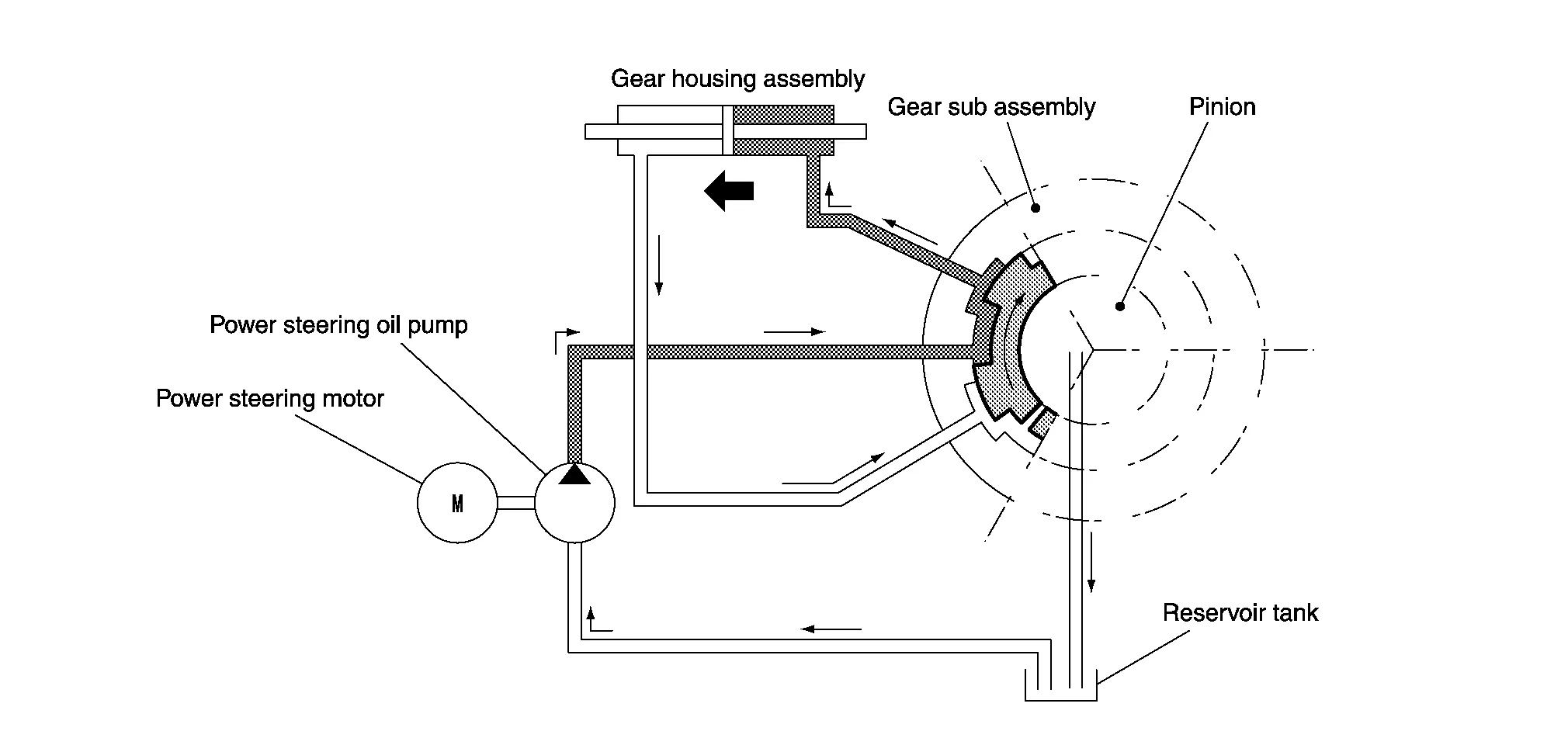
The hydraulic routes open from power steering pump to gear housing right side and from gear housing left side to reservoir tank, providing left directional assist force to the rack.
When Steering Wheel is Rotated to the Left
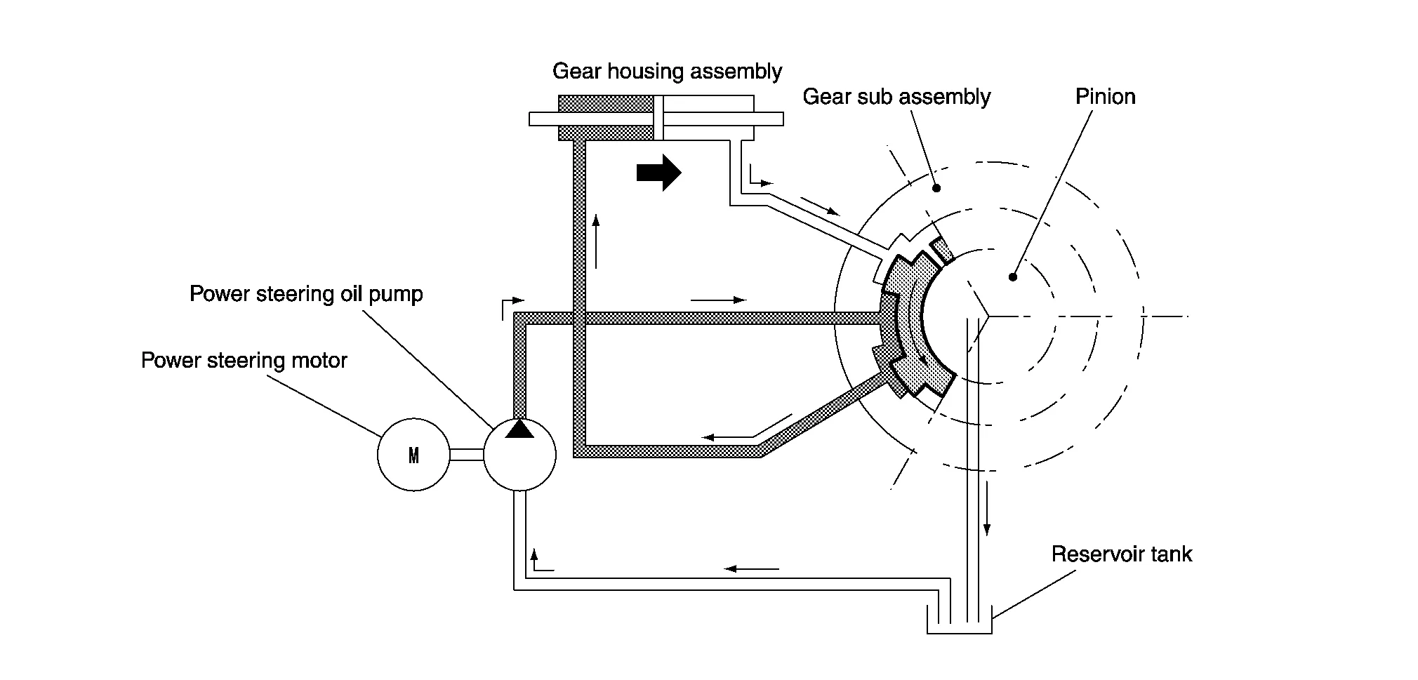
The hydraulic routes open from power steering pump to gear housing left side and from gear housing right side to reservoir tank, providing right directional assist force to the rack.
CONDITIONS FOR HYDRAULIC PUMP ELECTRIC POWER STEERING WARNING LAMP ON
When the hydraulic pump electric power steering system is operating and steering assist force is being generated, the hydraulic pump electric power steering warning lamp is OFF.
When the hydraulic pump electric power steering system is stopped by the fail-safe or protective function and steering assist force is not being generated, the hydraulic pump electric power steering warning lamp turns ON to inform the driver that the system is in the manual steering state.
When ignition switch ON, this lamp turns ON for lamp check (system check). When the system is operating normally, the lamp turns OFF after the engine starts.
| Condition | Hydraulic pump electric power steering warning lamp |
|---|---|
| Ignition switch ON (Lamp check) | ON |
| After engine start (steering assist force is generated) | OFF |
| When steering assist is stopped | ON |
| Name | Design | Layout/Function |
|---|---|---|
| Power steering warning lamp |  |
For layout, refer to Design. |
| For function, refer to System Description. |