Back Door Lock
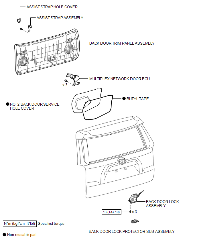
Removal REMOVAL PROCEDURE
1. REMOVE BACK DOOR LOCK PROTECTOR SUB-ASSEMBLY

2. REMOVE ASSIST STRAP HOLE COVER
3. REMOVE ASSIST STRAP ASSEMBLY
4. REMOVE BACK DOOR TRIM PANEL ASSEMBLY
5. REMOVE MULTIPLEX NETWORK DOOR ECU
6. REMOVE NO. 2 BACK DOOR SERVICE HOLE COVER
7. REMOVE BACK DOOR LOCK ASSEMBLY
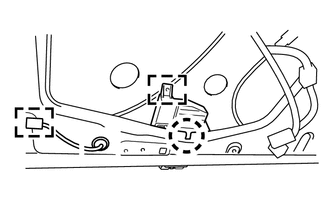
(a) Detach the 2 clamps and claw. |
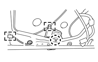 |
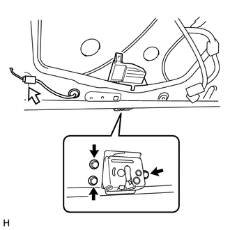
(b) Disconnect the connector. |
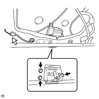 |
(c) Remove the 3 bolts and back door lock assembly.
Inspection INSPECTION PROCEDURE1. INSPECT BACK DOOR LOCK ASSEMBLY
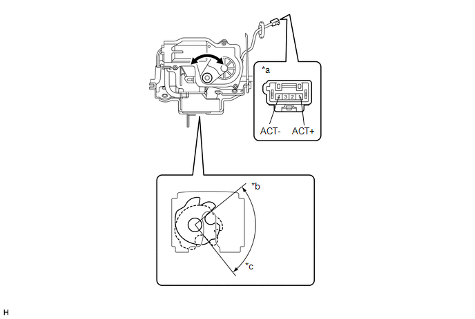
(a) Set the back door lock to the full-latch position.
(b) Apply battery voltage to the door motor connector and check the operation of the door lock motor.
OK:
Measurement Condition | Specified Condition |
|---|---|
Battery positive (+) → 1 (ACT+) Battery negative (-) → 4 (ACT-) |
Moves to open-latch position |
- If the result is not as specified, replace the back door lock assembly.
(c) Measure the resistance according to the value(s) in the table below.
Standard Resistance:
Tester Connection | Condition | Specified Condition |
|---|---|---|
3 (E) - 2 (S) |
Open-latch |
Below 1 Ω |
3 (E) - 2 (S) |
Full-latch |
10 kΩ or higher |
- If the result is not as specified, replace the back door lock assembly.
*a |
Component without harness connected (Back Door Lock Assembly) |
*b |
Full-latch |
*c |
Open-latch |
1. INSTALL BACK DOOR LOCK ASSEMBLY
(a) Install the back door lock assembly with the 3 bolts. Torque: 13 N·m {133 kgf·cm, 10 ft·lbf} |
 |
(b) Connect the connector.
(c) Attach the 2 clamps and claw. |
 |
2. INSTALL NO. 2 BACK DOOR SERVICE HOLE COVER

3. INSTALL MULTIPLEX NETWORK DOOR ECU
4. INSTALL BACK DOOR TRIM PANEL ASSEMBLY
5. INSTALL ASSIST STRAP ASSEMBLY
6. INSTALL ASSIST STRAP HOLE COVER
7. INSTALL BACK DOOR LOCK PROTECTOR SUB-ASSEMBLY
Test yourself
A quick Toyota 4Runner quiz: every answer comes with an explanation and a link to the manual page.