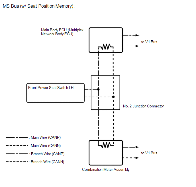
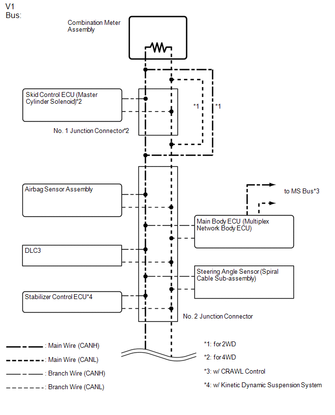
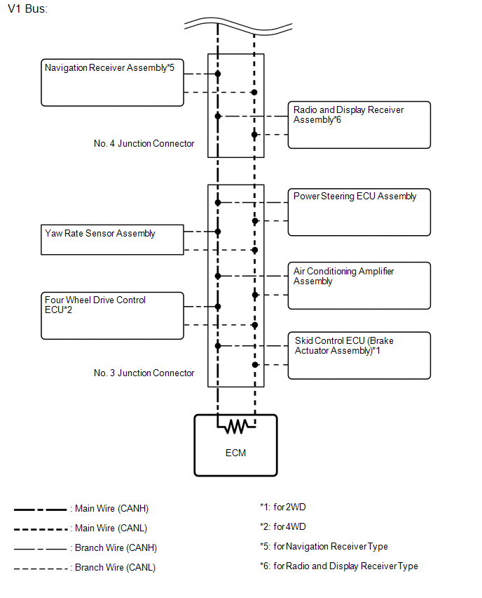
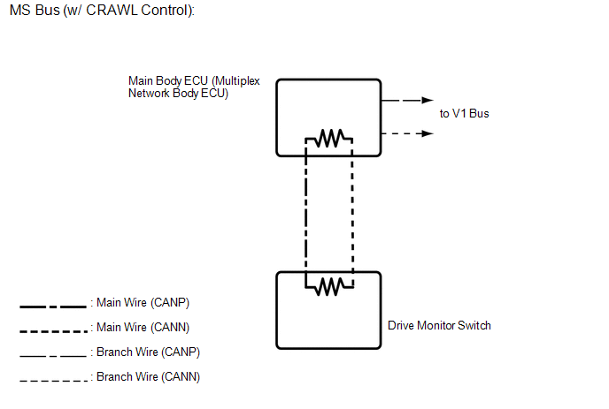
System Diagram
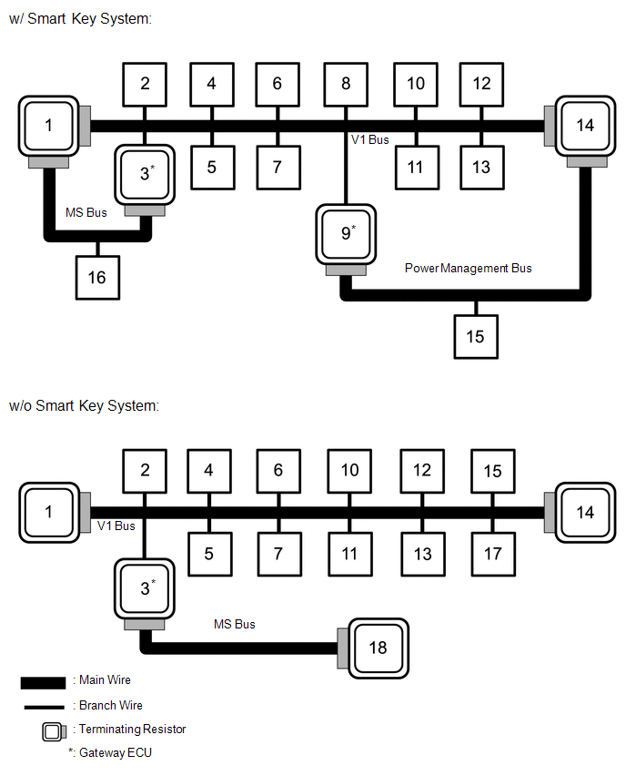 w/ Smart Key System
No. | ECU/Sensor Name |
|---|---|
1 |
Combination meter assembly |
2 |
Skid control ECU (master cylinder solenoid)*1 |
3 |
Main body ECU (multiplex network body ECU) |
4 |
Airbag sensor assembly |
5 |
Steering angle sensor (spiral cable sub-assembly) |
6 |
DLC3 |
7 |
Navigation receiver assembly*2 or radio and display receiver assembly*3 |
8 |
Certification ECU (smart key ECU assembly) |
9 |
Power management control ECU |
10 |
Yaw rate sensor assembly |
11 |
Power steering ECU assembly |
12 |
Four wheel drive control ECU*1 |
13 |
Skid control ECU (brake actuator assembly)*4 |
14 |
ECM |
15 |
Air conditioning amplifier assembly |
16 |
Front power seat switch LH*5 |
- *1: for 4WD
- *2: for Navigation Receiver Type
- *3: for Radio and Display Receiver Type
- *4: for 2WD
- *5: w/ Seat Position Memory
No. | ECU/Sensor Name |
|---|---|
1 |
Combination meter assembly |
2 |
Skid control ECU (master cylinder solenoid)*1 |
3 |
Main body ECU (multiplex network body ECU) |
4 |
Airbag sensor assembly |
5 |
Steering angle sensor (spiral cable sub-assembly) |
6 |
DLC3 |
7 |
Navigation receiver assembly*2 or radio and display receiver assembly*3 |
10 |
Yaw rate sensor assembly |
11 |
Power steering ECU assembly |
12 |
Four wheel drive control ECU*1 |
13 |
Skid control ECU (brake actuator assembly)*4 |
14 |
ECM |
15 |
Air conditioning amplifier assembly |
17 |
Stabilizer control ECU*5 |
18 |
Drive monitor switch*6 |
- *1: for 4WD
- *2: for Navigation Receiver Type
- *3: for Radio and Display Receiver Type
- *4: for 2WD
- *5: w/ Kinetic Dynamic Suspension System
- *6: w/ CRAWL Control
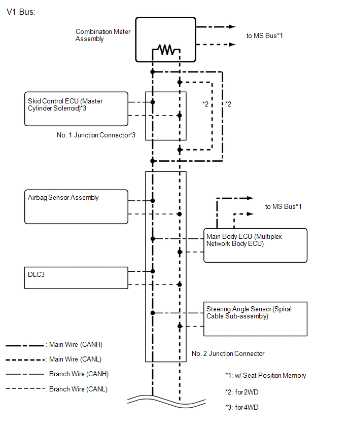
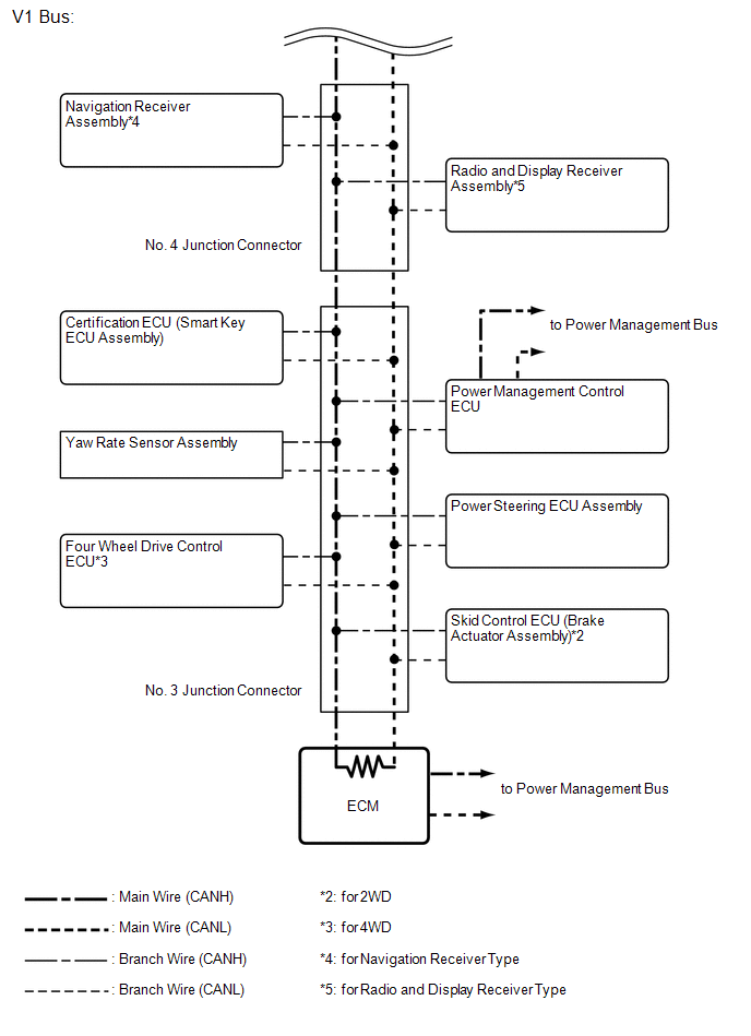
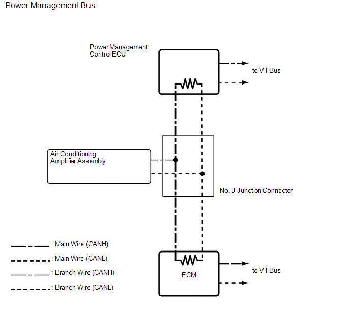
1. w/ Smart Key System:
2. w/o Smart Key System:
Test yourself
A quick Toyota 4Runner quiz: every answer comes with an explanation and a link to the manual page.