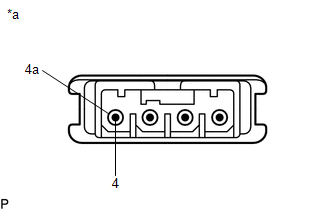
Inspection
INSPECTION
PROCEDURE
1. INSPECT NAVIGATION ANTENNA ASSEMBLY
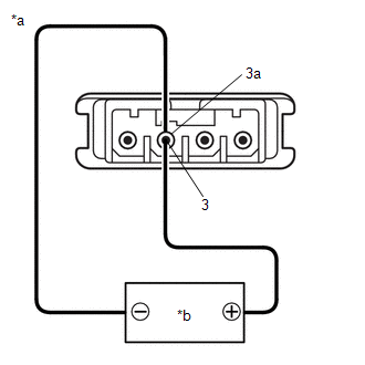
(a) Current consumption check: (GPS)
(1) Measure the current consumption according to the value(s) in the table below. Standard Current:
NOTICE: Do not apply 6 V or more between terminals 3 and 3a. HINT: If a stable power supply is not available, connect 4 nickel-metal hydride batteries (1.2 V each) or equivalent in series. If the result is not as specified, replace the navigation antenna assembly. |
|
(b) Resistance check: (Telephone Sub)
(1) Measure the resistance according to the value(s) in the table below. Standard Resistance:
If the result is not as specified, replace the navigation antenna assembly. |
|