Installation
INSTALLATION
COMPONENTS (INSTALLATION)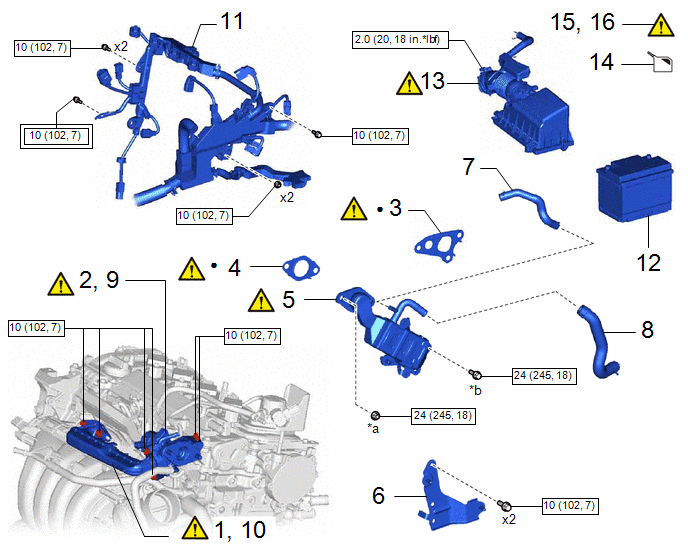
Procedure | Part Name Code |  |  |  |
|
|---|---|---|---|---|---|
1 |
LOOSEN NO. 1 EGR PIPE SUB-ASSEMBLY |
25601 |
 |
- |
- |
2 |
LOOSEN EGR VALVE ASSEMBLY |
25620 |
|
- |
- |
3 |
NO. 1 EGR COOLER GASKET |
25685 |
|
- |
- |
4 |
EGR VALVE GASKET |
25627 |
|
- |
- |
5 |
EGR COOLER ASSEMBLY |
25680 |
|
- |
- |
6 |
WIRE HARNESS CLAMP BRACKET |
- |
- |
- |
- |
7 |
NO. 4 WATER BY-PASS HOSE |
16281 |
- |
- |
- |
8 |
NO. 3 WATER BY-PASS HOSE |
16267 |
- |
- |
- |
9 |
TIGHTEN EGR VALVE ASSEMBLY |
25620 |
|
- |
- |
10 |
TIGHTEN NO. 1 EGR PIPE SUB-ASSEMBLY |
25601 |
|
- |
- |
11 |
ENGINE WIRE |
82121 |
- |
- |
- |
12 |
AUXILIARY BATTERY |
- |
- |
- |
- |
13 |
AIR CLEANER CAP WITH AIR CLEANER HOSE |
- |
|
- |
- |
14 |
ADD ENGINE COOLANT |
- |
- |
|
- |
15 |
INSPECT FOR COOLANT LEAK |
- |
|
- |
- |
16 |
INSPECT FOR EXHAUST GAS LEAK |
- |
|
- |
- |
*a |
x2 or x3 |
*b |
x3 or x2 |
 |
Tightening torque for "Major areas involving basic vehicle performance such as moving/turning/stopping" : N*m (kgf*cm, ft.*lbf) |
 |
N*m (kgf*cm, ft.*lbf): Specified torque |
● |
Non-reusable part |
- |
- |
NOTICE:
This procedure includes the installation of small-head bolts. Refer to Small-Head Bolts of Basic Repair Hint to identify the small-head bolts.
Click here
PROCEDURE
1. LOOSEN NO. 1 EGR PIPE SUB-ASSEMBLY
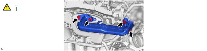
(1) Using an 8 mm socket wrench, loosen the 4 bolts of the No. 1 EGR pipe sub-assembly.
NOTICE:
- As the bolts of the No. 1 EGR pipe sub-assembly are only to be loosened, it is not necessary to replace the EGR inlet gasket and EGR valve adapter gasket.
- If the No. 1 EGR pipe sub-assembly is removed, it is necessary to replace the EGR inlet gasket and EGR valve adapter gasket with new ones.
2. LOOSEN EGR VALVE ASSEMBLY
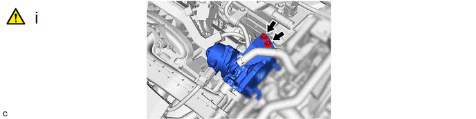
(1) Using an 8 mm socket wrench, loosen the 2 bolts EGR valve assembly.
3. INSTALL NO. 1 EGR COOLER GASKET
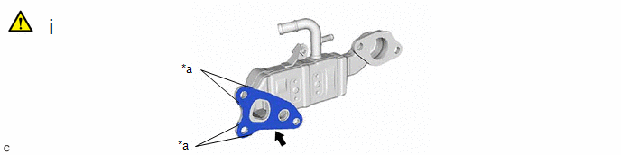
*a |
Claw |
- |
- |
(1) Install a new No. 1 EGR cooler gasket to the EGR cooler assembly.
NOTICE:
Make sure that the claws of the No. 1 EGR cooler gasket are toward the EGR cooler assembly side.
4. INSTALL EGR VALVE GASKET
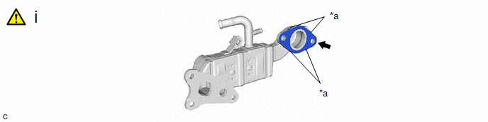
*a |
Claw |
- |
- |
(1) Install a new EGR valve gasket to the EGR cooler assembly.
NOTICE:
Make sure that the claws of the EGR valve gasket are toward the EGR cooler assembly side.
5. INSTALL EGR COOLER ASSEMBLY
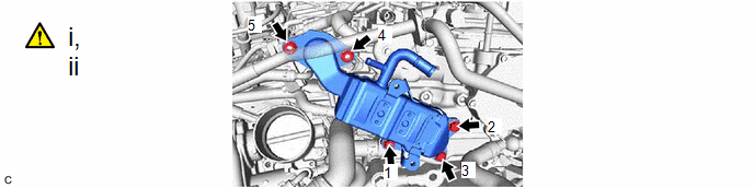
[The illustrations are representative examples, and details may differ.]
(1) Temporarily install the EGR cooler assembly to the cylinder head sub-assembly and EGR valve assembly with the bolts and nuts.
(2) Tighten the bolts and nuts in the order shown in the illustration.
Torque:
24 N·m {245 kgf·cm, 18 ft·lbf}
6. INSTALL WIRE HARNESS CLAMP BRACKET
Torque:
10 N·m {102 kgf·cm, 7 ft·lbf}
7. CONNECT NO. 4 WATER BY-PASS HOSE
8. CONNECT NO. 3 WATER BY-PASS HOSE
9. TIGHTEN EGR VALVE ASSEMBLY
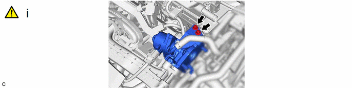
(1) Using an 8 mm socket wrench, tighten the 2 bolts of the EGR valve assembly.
Torque:
10 N·m {102 kgf·cm, 7 ft·lbf}
10. TIGHTEN NO. 1 EGR PIPE SUB-ASSEMBLY
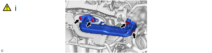
(1) Using an 8 mm socket wrench, tighten the 4 bolts of the No. 1 EGR pipe sub-assembly.
Torque:
10 N·m {102 kgf·cm, 7 ft·lbf}
11. CONNECT ENGINE WIRE
Torque:
10 N·m {102 kgf·cm, 7 ft·lbf}
12. INSTALL AUXILIARY BATTERY
Click here
13. INSTALL AIR CLEANER CAP WITH AIR CLEANER HOSE
|
Click here |
14. ADD ENGINE COOLANT
Click here
15. INSPECT FOR COOLANT LEAK
Click here
16. INSPECT FOR EXHAUST GAS LEAK
Click here