Installation
INSTALLATION
COMPONENTS (INSTALLATION)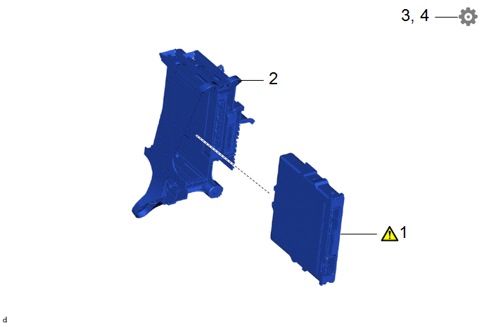
Procedure | Part Name Code |  |  |  |
|
|---|---|---|---|---|---|
1 |
ENGINE STOP AND START ECU |
89261A |
 |
- |
- |
2 |
POWER DISTRIBUTION BOX ASSEMBLY WITH MULTIPLEX NETWORK BODY ECU |
- |
- |
- |
- |
3 |
PERFORM REGISTRATION |
- |
- |
- |
|
4 |
UPDATE ECU SECURITY KEY |
- |
- |
- |
|
NOTICE:
After performing the update ECU security key procedure, make sure to perform the initialization procedure for when the cable has been disconnected and reconnected to the negative (-) auxiliary battery terminal.
PROCEDURE
1. INSTALL ENGINE STOP AND START ECU
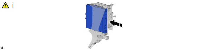
(1) Engage the 2 claws and install the engine stop and start ECU to the ECU integration box RH.
NOTICE:
Make sure that the engine stop and start ECU is securely installed.
2. INSTALL POWER DISTRIBUTION BOX ASSEMBLY WITH MULTIPLEX NETWORK BODY ECU
Click here
3. UPDATE ECU SECURITY KEY
Click here
4. PERFORM REGISTRATION
Click here