Installation
INSTALLATION
COMPONENTS (INSTALLATION)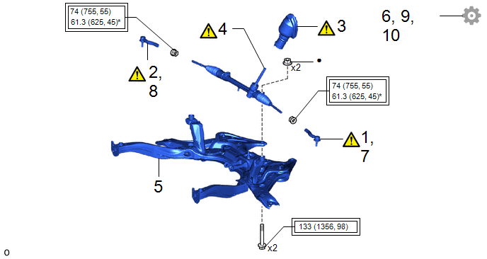
Procedure | Part Name Code |  |  |  |
|
|---|---|---|---|---|---|
1 |
TEMPORARILY TIGHTEN TIE ROD END SUB-ASSEMBLY LH |
45047 |
 |
- |
- |
2 |
TEMPORARILY TIGHTEN TIE ROD END SUB-ASSEMBLY RH |
45046 |
|
- |
- |
3 |
NO. 1 STEERING COLUMN HOLE COVER SUB-ASSEMBLY |
45025D |
|
- |
- |
4 |
STEERING LINK ASSEMBLY |
- |
|
- |
- |
5 |
FRONT SUSPENSION CROSSMEMBER SUB-ASSEMBLY |
51201F |
- |
- |
- |
6 |
INSPECT AND ADJUST FRONT WHEEL ALIGNMENT |
- |
- |
- |
|
7 |
FULLY TIGHTEN TIE ROD END SUB-ASSEMBLY LH |
45047 |
|
- |
- |
8 |
FULLY TIGHTEN TIE ROD END SUB-ASSEMBLY RH |
45046 |
|
- |
- |
9 |
PERFORM END POSITION INITIAL SETTING |
- |
- |
- |
|
10 |
PERFORM INITIALIZATION |
- |
- |
- |
|
 |
Tightening torque for "Major areas involving basic vehicle performance such as moving/turning/stopping": N*m (kgf*cm, ft.*lbf) |
● |
Non-reusable part |
* |
For use with SST |
- |
- |
PROCEDURE
1. TEMPORARILY TIGHTEN TIE ROD END SUB-ASSEMBLY LH

*a |
Matchmark |
- |
- |
(1) Temporarily install the lock nut and tie rod end sub-assembly LH to the steering gear assembly until the matchmarks are aligned.
HINT:
After adjusting the toe-in, tighten the lock nut.
2. TEMPORARILY TIGHTEN TIE ROD END SUB-ASSEMBLY RH
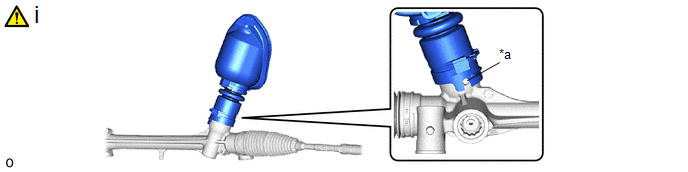
3. INSTALL NO. 1 STEERING COLUMN HOLE COVER SUB-ASSEMBLY
*a |
Protrusion |
- |
- |
(1) Align the protrusion of the steering link assembly with the hole of the No. 1 steering column hole cover sub-assembly, and install the No. 1 steering column hole cover sub-assembly to the steering link assembly.
4. INSTALL STEERING LINK ASSEMBLY

 |
Front of the Vehicle |
- |
- |
(1) Install the steering link assembly to the front suspension crossmember sub-assembly with the 2bolts and 2 new nuts.
Torque:
133 N·m {1356 kgf·cm, 98 ft·lbf}
NOTICE:
- Because the nut has its own stopper, do not turn the nut. Tighten the bolt with the nut secured.
- Make sure to tighten the bolts starting from the right side of the vehicle.
5. INSTALL FRONT SUSPENSION CROSSMEMBER SUB-ASSEMBLY
Click here
6. INSPECT AND ADJUST FRONT WHEEL ALIGNMENT
Click here
7. FULLY TIGHTEN TIE ROD END SUB-ASSEMBLY LH
*a |
Torque Wrench Fulcrum Length |
- |
- |
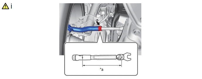
(1) Using SST, tighten the tie rod end sub-assembly lock nut.
SST: 09612-24014
09617-24011
Torque:
Specified Tightening Torque :
74 N·m {755 kgf·cm, 55 ft·lbf}
HINT:
- Calculate the torque wrench reading when changing the fulcrum length of the torque wrench.
Click here
- When using SST (fulcrum length of 52.7 mm (2.07 in.)) + torque wrench (fulcrum length of 255 mm (10.04 in.)): 61.3 N*m (625 kgf*cm, 45 ft.*lbf)
8. FULLY TIGHTEN TIE ROD END SUB-ASSEMBLY RH
9. PERFORM END POSITION INITIAL SETTING
Click here
10. PERFORM INITIALIZATION
- Parking Assist Monitor System:
Click here
- Automatic headlight beam level control system:
Click here