Reassembly
REASSEMBLY
COMPONENTS (REASSEMBLY)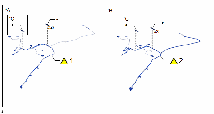
Procedure | Part Name Code |  |  |  |
|
|---|---|---|---|---|---|
1 |
NO. 1 ROOF WIRE |
82171 |
 |
- |
- |
2 |
NO. 1 ROOF WIRE |
82171 |
|
- |
- |
*A |
w/o Sliding Roof |
*B |
w/ Sliding Roof |
*C |
w/ EC Mirror |
- |
- |
● |
Non-reusable part |
- |
- |
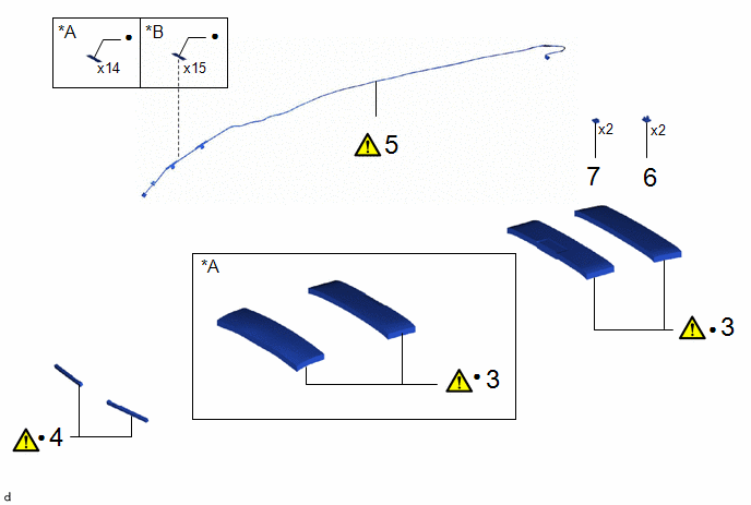
Procedure | Part Name Code | | | |
|
|---|---|---|---|---|---|
3 |
ROOF HEADLINING PAD |
63351B |
|
- |
- |
4 |
NO. 2 ROOF SILENCER PAD |
63342 |
|
- |
- |
5 |
NO. 2 ANTENNA CORD SUB-ASSEMBLY |
86101J |
|
- |
- |
6 |
MICROPHONE CASE |
85255F |
- |
- |
- |
7 |
TELEPHONE MICROPHONE ASSEMBY |
86730A |
- |
- |
- |
*A |
w/o Sliding Roof |
*B |
w/ Sliding Roof |
● |
Non-reusable part |
- |
- |
PROCEDURE
1. INSTALL NO. 1 ROOF WIRE (w/o Sliding Roof)
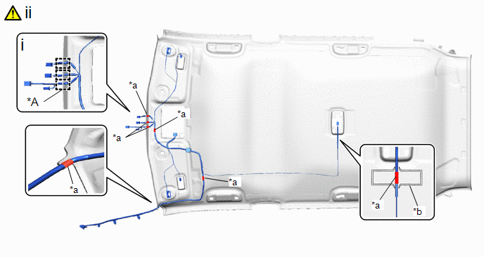
*A |
w/ EC Mirror |
- |
- |
*a |
Marking Tape |
*b |
Marking |
(1) Engage the each guide.
(2) Align the marking tape on the No. 1 roof wire with the roof headlining marking.
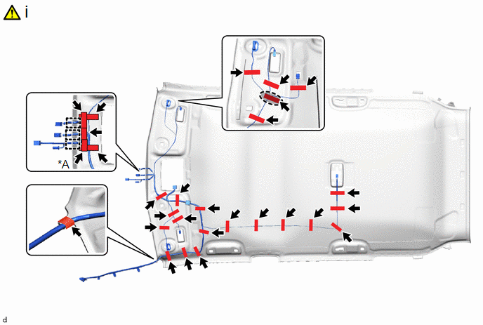
*A |
w/ EC Mirror |
- |
- |
 |
Adjustment Area |
- |
- |
(1) Install the No. 1 roof wire to the roof headlining assembly with new adhesive tapes.
NOTICE:
- Apply the tape securely in place.
- Do not touch the adhesive surface when applying the tape to prevent adhesion failure.
HINT:
Adjust the slack of the No. 1 roof wire as shown in the adjustment area of illustration.
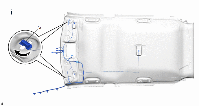
*a |
Visor Connector |
- |
- |
 |
Install in this Direction |
- |
- |
(1) Connect the 2 visor connectors as shown in the illustration.
2. INSTALL NO. 1 ROOF WIRE (w/ Sliding Roof)
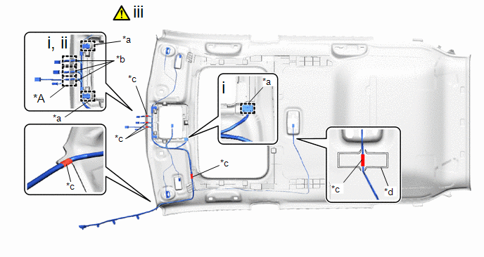
*A |
w/ EC Mirror |
- |
- |
*a |
Clamp |
*b |
Guide |
*c |
Marking Tape |
*d |
Marking |
(1) Engage the clamps
(2) Engage the each guide.
(3) Align the marking tape on the No. 1 roof wire with the roof headlining markings.
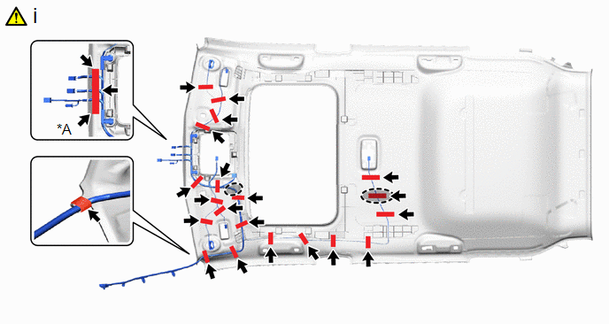
*A |
w/ EC Mirror |
- |
- |
|
Adjustment Area |
- |
- |
(1) Install the No. 1 roof wire to the roof headlining assembly with new adhesive tapes.
NOTICE:
- Apply the tape securely in place.
- Do not touch the adhesive surface when applying the tape to prevent adhesion failure.
HINT:
Adjust the slack of the No. 1 roof wire as shown in the adjustment area of illustration.
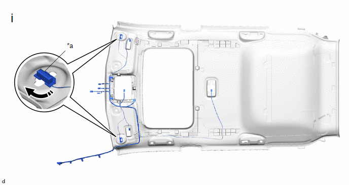
*a |
Visor Connector |
- |
- |
|
Install in this Direction |
- |
- |
(1) Connect the visor connector as shown in the illustration.
3. INSTALL ROOF HEADLINING PAD
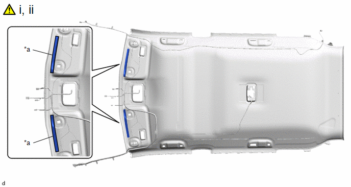
*a |
Marking |
- |
- |
(1) Remove the release paper from 2 new roof headlining pads.
HINT:
After removing the release paper, keep the exposed adhesive free from foreign matter.
(2) Align the 2 roof headlining pads with the markings on the roof headlining assembly and install it as shown in the illustration.
4. INSTALL NO. 2 ROOF SILENCER PAD
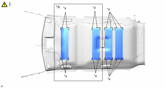
*A |
w/o Sliding Roof |
- |
- |
*a |
Marking |
- |
- |
(1) Align new No. 2 roof headlining pads with the markings on the roof headlining assembly and install them using hot-melt glue as shown in the illustration.
5. INSTALL NO. 2 ANTENNA CORD SUB-ASSEMBLY
|
Click here |
6. INSTALL MICROPHONE CASE
7. INSTALL TELEPHONE MICROPHONE ASSEMBLY