Sliding Roof Switch Assembly
Removal
REMOVAL
COMPONENTS (REMOVAL)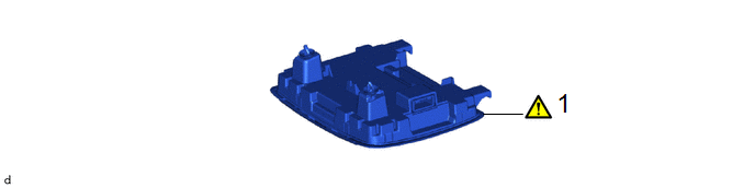
Procedure | Part Name Code |  |  |  |
|
|---|---|---|---|---|---|
1 |
MAP LIGHT ASSEMBLY |
81260A |
 |
- |
- |
PROCEDURE
1. REMOVE MAP LIGHT ASSEMBLY
Click here
Inspection
INSPECTION
PROCEDURE
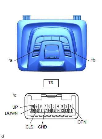
1. INSPECT SLIDING ROOF SWITCH (MAP LIGHT ASSEMBLY)
(a) Check the sliding roof switch.
(1) Measure the resistance according to the value(s) in the table below. Standard Resistance:
If the result is not as specified, replace the sliding roof switch (map light assembly). |
|
Installation
INSTALLATION
COMPONENTS (INSTALLATION)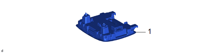
Procedure | Part Name Code |  |  |  |
|
|---|---|---|---|---|---|
1 |
MAP LIGHT ASSEMBLY |
81260A |
- |
- |
- |
PROCEDURE
1. INSTALL MAP LIGHT ASSEMBLY