Unlock Warning Switch
Removal
REMOVAL
COMPONENTS (REMOVAL)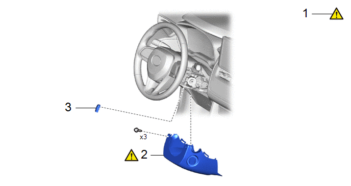
Procedure | Part Name Code |  |  |  |
|
|---|---|---|---|---|---|
1 |
STEERING WHEEL POSITION |
- |
 |
- |
- |
2 |
LOWER STEERING COLUMN COVER |
45287 |
|
- |
- |
3 |
UNLOCK WARNING SWITCH ASSEMBLY |
84052 |
- |
- |
- |
PROCEDURE
1. ADJUST STEERING WHEEL POSITION
|
Click here |
2. REMOVE LOWER STEERING COLUMN COVER
|
Click here |
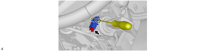
3. REMOVE UNLOCK WARNING SWITCH ASSEMBLY
Inspection
INSPECTION
PROCEDURE
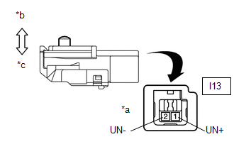
1. INSPECT UNLOCK WARNING SWITCH ASSEMBLY
(a) Measure the resistance according to the value(s) in the table below. Standard Resistance:
If the result is not as specified, replace the unlock warning switch assembly. |
|
Installation
INSTALLATION
COMPONENTS (INSTALLATION)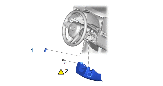
Procedure | Part Name Code |  |  |  |
|
|---|---|---|---|---|---|
1 |
UNLOCK WARNING SWITCH ASSEMBLY |
84052 |
- |
- |
- |
2 |
LOWER STEERING COLUMN COVER |
45287 |
 |
- |
- |
PROCEDURE
1. INSTALL UNLOCK WARNING SWITCH ASSEMBLY
2. INSTALL LOWER STEERING COLUMN COVER
|
Click here |