Replacement
1. DISCHARGE FUEL SYSTEM PRESSURE (See page 11-35 )
2. REMOVE DECK BOARD SUB-ASSY
3. REMOVE REAR SEAT TRACK BRACKET COVER OUTER
4. REMOVE REAR SEAT ASSY RH (See page 72-35 )
5. REMOVE REAR SEAT ASSY LH (See page 72-28 )
6. REMOVE REAR DOOR SCUFF PLATE LH
7. REMOVE REAR FLOOR SERVICE HOLE COVER (See page 11-55 )
8. REMOVE FUEL SUCTION TUBE ASSY W/ PUMP & GAGE (See page 11-55 )
9. DRAIN FUEL
10. REMOVE PROPELLER W/CENTER BEARING SHAFT ASSY (4WD TYPE) (See page 30-4 )
11. REMOVE EXHAUST PIPE ASSY CENTER (See page 15-5 )
12. REMOVE FRONT FLOOR HEAT INSULATOR NO.3 (See page 12-28 )
13. REMOVE EXHAUST PIPE SUPPORT BRACKET NO.4 (4WD TYPE)
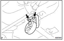
(a) Remove the 2 bolts and support bracket.
14. REMOVE FUEL TUBE PROTECTOR NO.1
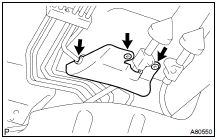
(a) Remove the 2 clips and unfasten the claw, and remove the tube protector.
15. REMOVE FUEL TANK PROTECTOR NO.1
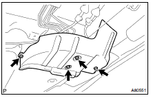
(a) Remove the 4 nuts and fuel tank protector.
16. REMOVE FUEL TANK PROTECTOR SUB-ASSY NO.1
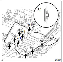
(a) Remove the 3 clips ( 1), 6 nuts and tank protector.
17. REMOVE FUEL TANK ASSY
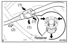
(a) Disconnect the fuel pump tube.
- Pinch the projection of the retainer to remove the lock claws and pull down it as shown in the illustration.
- Pull out the fuel pump tube.
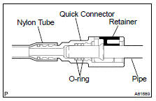
NOTICE:
- Before this operation, check the connector for dirt, mud or other contamination. Clean if necessary.
- Be careful of mud. The connector's O-ring, which seals the pipe and connector, becomes contaminated easily.
- Do not use any tool in this operation.
- Do not bend or twist the nylon tube. Protect the connector by covering it with a vinyl or plastic bag.
- When the pipe and connector are stuck, push and pull the connector to release it. Then pull out the connector from the pipe.
(b) Disconnect the fuel tank vent hose hose.
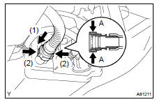
- Push the connector deep into the charcoal canister to release the locking tab.
- Pinch portion A.
- Pull out the connector.
(c) Disconnect the fuel tank breather tube No.3.
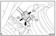
- Lower the connector checker slightly.
- Pinch the tube connector.
- Pull out the breather tube.
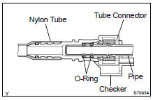
NOTICE:
- Before this operation, check the connector for dirt, mud or other contamination. Clean if necessary.
- Be careful of mud. The connector's O-ring, which seals the pipe and connector, becomes contaminated easily.
- Do not use any tool in this operation.
- Do not bend or twist the nylon tube. Protect the connector by covering it with a vinyl or plastic bag.
- When the pipe and connector are stuck, push and pull the connector to release it. Then pull out the connector from the pipe.
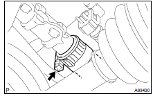
(d) Loosen the hose clamp bolt and disconnect the fuel tank to filler pipe hose. (e) Disconnect the fuel tank wire connector. (f) Remove the connector clamp. (g) Set up a transmission jack under the fuel tank. (h) Remove the 4 bolts and 2 fuel tank bands. (i) Remove the 2 nuts.
(j) Operate the transmission jack and remove the fuel tank.
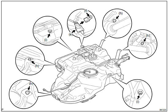
18. REMOVE FUEL PUMP TUBE SUB-ASSY
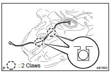
(a) Unfasten the 2 claws and remove the tube.
19. REMOVE FUEL TANK TO FILLER PIPE HOSE
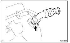
(a) Loosen the hose clamp bolt and remove the hose.
20. REMOVE FUEL TANK WIRE
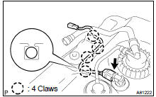
(a) Disconnect the vapor pressure sensor connector.
(b) Unfasten the 4 claws and remove the wire.
21. REMOVE VAPOR PRESSURE SENSOR ASSY
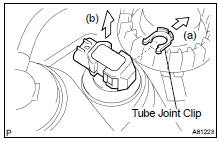
(a) Remove the tube joint clip.
(b) Pull out the vapor pressure sensor.
22. REMOVE FUEL TANK VENT HOSE
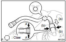
(a) Push the connector deep into the charcoal canister to release the locking tab. (b) Pinch portion A. (c) Pull out the connector.
(d) Unfasten the claw and remove the vent hose.
23. REMOVE TANK SUCTION TUBE SUPPORT
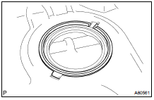
(a) Remove the tube support from the fuel tank.
24. REMOVE FUEL TANK SIDE PLATE
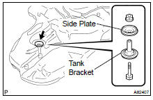
(a) Remove the bolt and nut, and then remove the fuel tank side plate and the fuel tank bracket.
25. REMOVE FUEL TANK CUSHION SET

(a) Remove the cushion set and cushion No. 5.
26. INSTALL FUEL TANK CUSHION SET
27. INSTALL FUEL TANK SIDE PLATE Torque: 30 NVm (306 kgfVcm, 22 ftVlbf)
28. INSTALL TANK SUCTION TUBE SUPPORT
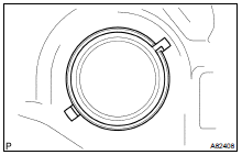
(a) Install a new tube support as shown in the illustration.
29. INSTALL FUEL TANK VENT HOSE
30. INSTALL VAPOR PRESSURE SENSOR ASSY
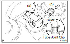
(a) Push and hold down the vapor pressure sensor.
(b) Install the fuel tube joint clip to the sensor.
NOTICE:
- Check that there are no scratches or foreign objects on the connecting parts.
- Check that the fuel tube joint is fully inserted.
- Check that the fuel tube joint clip is on the collar of the fuel tube joint.
- After installing the tube joint clip, check if the fuel joint is securely connected by trying to pull it.
31. INSTALL FUEL TANK WIRE
32. INSTALL FUEL TANK TO FILLER PIPE HOSE
33. INSTALL FUEL PUMP TUBE SUB-ASSY
34. INSTALL FUEL TANK ASSY
(a) Set up the fuel tank to the transmission jack.(b) Operate the transmission jack and install the fuel tank.
(c) Tighten the 2 nuts.
Torque: 20 NVm (200 kgfVcm, 14 ftVlbf) (d) Install the 2 fuel tank bands with the 4 bolts.
Torque: 39 NVm (400 kgfVcm, 29 ftVlbf) (e) Install the connector clamp. (f) Connect the fuel tank wire connector. (g) Connect the fuel tank to filler pipe hose. (h) Connect the fuel tank breather tube No. 3.(1) Push the quick connector to the pipe until it makes "click" sound.
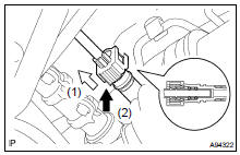
NOTICE:
- Check if there is any damage or foreign objects on the connected part.
- After connecting, check if the quick connector and the pipe are securely connected by trying to pull them apart.
- Return the connecter checker to its original position.
(i) Connect the fuel tank vent hose.

(j) Connect the fuel pump tube.
- Push the quick connector in the direction of the white arrow.
NOTICE:
- Check if there is any damage or foreign objects on the connected part.
- After connecting, check if the quick connector and the pipe are securely connected by trying to pull them.
- Push up on the retainer until the claws lock.
35. INSTALL FUEL TANK PROTECTOR SUB-ASSY NO.1
(a) Install the tank protector with the 6 nuts.
Torque: 5.5 NVm (56 kgfVcm, 49 in.Vlbf) (b) Install 3 new clips.
36. INSTALL FUEL TANK PROTECTOR NO.1 Torque: 5.5 NVm (56 kgfVcm, 49 in.Vlbf)
37. INSTALL FUEL TUBE PROTECTOR NO.1
38. INSTALL EXHAUST PIPE SUPPORT BRACKET NO.4 (4WD TYPE) Torque: 22 NVm (224 kgfVcm, 16 ftVlbf)