Park assist / monitoring
Display Signal Circuit between Radio and Navigation Assembly and Television Camera Assembly
In this manual: Park assist / monitoring
8steps
~48min
2/5difficulty
Done 0 of 8
DESCRIPTION
This is the display signal circuit of the television camera assembly.
WIRING DIAGRAM

INSPECTION PROCEDURE
1 CHECK HARNESS AND CONNECTOR (RADIO AND NAVIGATION ASSEMBLY - TELEVISION CAMERA ASSEMBLY)
- Disconnect the R10 connector from the radio and navigation assembly.
- Disconnect the T10 connector from the television camera assembly.
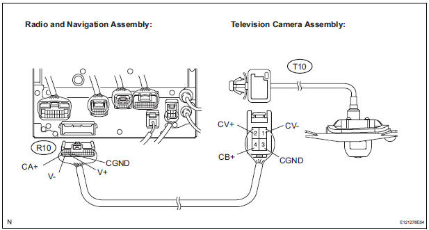
- Measure the resistance according to the value(s) in the table below.
Standard resistance

2 INSPECT RADIO AND NAVIGATION ASSEMBLY
- Reconnect the radio and navigation assembly R10 connector.

- Measure the voltage according to the value(s) in the table below
Standard voltage

3 INSPECT TELEVISION CAMERA ASSEMBLY
- Reconnect the radio and navigation assembly R10 connector and the television camera assembly T10 connector.
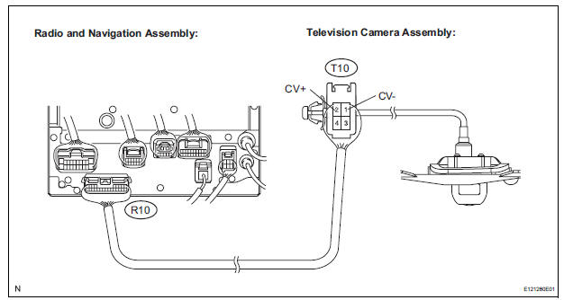
- Check the waveform of the television camera assembly using an oscilloscope.
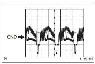
- Measurement terminal: CV+ - CVMeasurement setting: 0.2 V/DIV, 0.2 μs/DIV Condition: Ignition switch ON, Shift lever in R range
OK: Pulses as shown in the illustration.
PROCEED TO NEXT CIRCUIT INSPECTION SHOWN IN PROBLEM SYMPTOMS TABLE
Test yourself
A quick Toyota Sienna quiz: every answer comes with an explanation and a link to the manual page.
Was this page helpful?