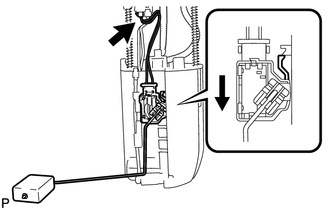
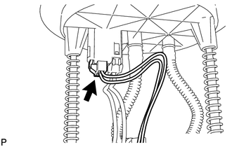
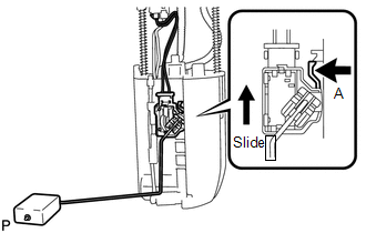
Fuel Sender Gauge Assembly
ComponentsCOMPONENTSILLUSTRATION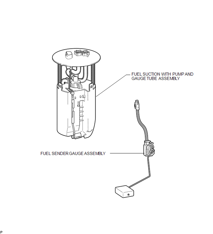
InspectionINSPECTIONPROCEDURE1. INSPECT FUEL SENDER GAUGE ASSEMBLY 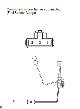
(a) Check that the float moves smoothly between F and E. (b) Measure the resistance according to the value(s) in the table below. Standard Resistance:
If the result is not as specified, replace the fuel sender gauge assembly. InstallationINSTALLATIONPROCEDURE1. INSTALL FUEL SENDER GAUGE ASSEMBLY
(b) Connect the fuel sender gauge connector. 2. INSTALL FUEL SUCTION WITH PUMP AND GAUGE TUBE ASSEMBLY (a) Install the fuel suction with pump and gauge tube (See page RemovalREMOVALPROCEDURE1. REMOVE FUEL SUCTION WITH PUMP AND GAUGE TUBE ASSEMBLY (a) Remove the fuel suction with pump and gauge tube (See page 2. REMOVE FUEL SENDER GAUGE ASSEMBLY
|