Engine, Hybrid System
Installation
Tightening torque found on this page
INSTALLATION
PROCEDURE
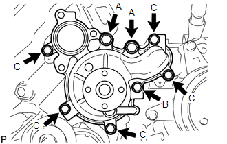
1. INSTALL WATER PUMP ASSEMBLY
(a) Install a new gasket and the water pump assembly with the 8 bolts shown in the illustration.
Torque:
for bolt A :
47 N·m {479 kgf·cm, 35 ft·lbf}
for bolt B :
23 N·m {235 kgf·cm, 17 ft·lbf}
for bolt C :
20 N·m {204 kgf·cm, 15 ft·lbf} |
 |
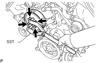
2. INSTALL WATER PUMP PULLEY
(a) Temporarily install the water pump pulley with the 4 bolts.
(b) Using SST, hold the water pump pulley and tighten the 4 bolts.
SST: 09960-10010
09962-01000
09963-01000
Torque:
21 N·m {214 kgf·cm, 15 ft·lbf} |
 |
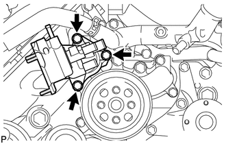
3. INSTALL WATER INLET HOUSING
(a) Install a new gasket to the water pump assembly.
(b) Install the water inlet housing with the 3 bolts.
Torque:
21 N·m {214 kgf·cm, 15 ft·lbf} |
 |
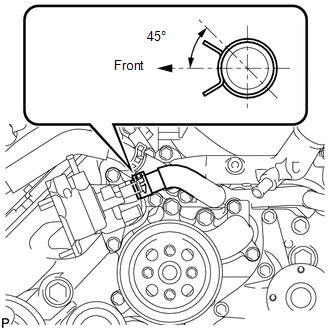
4. CONNECT NO. 5 WATER BY-PASS HOSE
(a) Connect the No. 5 water by-pass hose.
HINT:
The direction of hose clamp is indicated in the illustration. |
 |
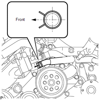
5. CONNECT NO. 8 WATER BY-PASS HOSE
(a) Connect the No. 8 water by-pass hose.
HINT:
The direction of hose clamp is indicated in the illustration. |
 |
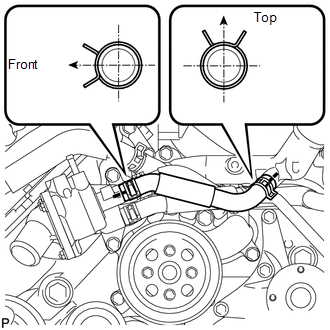
6. INSTALL NO. 1 WATER BY-PASS HOSE
(a) Install the No. 1 water by-pass hose.
HINT:
The direction of hose clamp is indicated in the illustration. |
 |
7. INSTALL WATER INLET SUB-ASSEMBLY WITH THERMOSTAT
(See page  )
8. INSTALL FAN SHROUD
(See page ) |
Was this page helpful?