Vehicle Interior
Sliding Roof Switch Assembly(for Crewmax)
Components
COMPONENTS
ILLUSTRATION 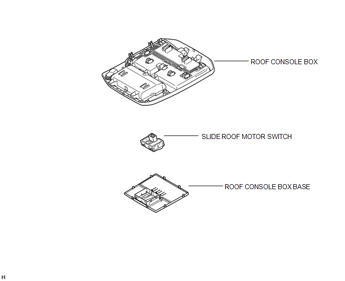
Inspection
INSPECTION
PROCEDURE
1. INSPECT SLIDE ROOF MOTOR SWITCH 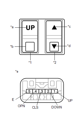
(a) Measure the resistance according to the value(s) in the table below.
Standard Resistance:
Tester Connection | Switch Condition | Specified Condition |
1 (UP) - 5 (E) |
Tilt switch is pressed to up |
Below 1 Ω |
1 (UP) - 5 (E) |
Tilt switch is not pressed to up |
10 kΩ or higher |
2 (DOWN) - 5 (E) |
Tilt switch is pressed to down |
Below 1 Ω |
2 (DOWN) - 5 (E) |
Tilt switch is not pressed to down |
10 kΩ or higher |
4 (OPN) - 5 (E) |
Slide switch is pressed to open |
Below 1 Ω |
4 (OPN) - 5 (E) |
Slide switch is not pressed to open |
10 kΩ or higher |
3 (CLS) - 5 (E) |
Slide switch is pressed to close |
Below 1 Ω |
3 (CLS) - 5 (E) |
Slide switch is not pressed to close |
10 kΩ or higher |
If the result is not as specified, replace the slide roof motor switch. Text in Illustration
*1 |
Tilt Switch |
*2 |
Slide Switch |
*a |
Up |
*b |
Down |
*c |
Open |
*d |
Close |
*e |
Component without harness connected
(Slide Roof Motor Switch) |
Installation
INSTALLATION
PROCEDURE
1. INSTALL SLIDE ROOF MOTOR SWITCH
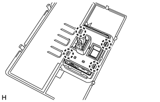
(a) Attach the 4 claws to install the slide roof motor switch.
(b) Connect the connector.
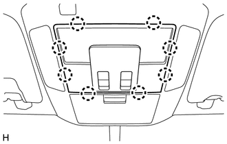
(c) Attach the 8 claws to install the roof console box base. |
 |
Removal
REMOVAL
PROCEDURE
1. REMOVE SLIDE ROOF MOTOR SWITCH
(a) Put protective tape around the roof console box base. Text in Illustration |
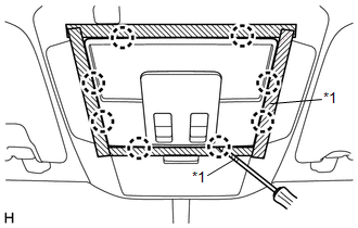 |
(b) Using a screwdriver, detach the 8 claws.
HINT:
Tape the screwdriver tip before use.
(c) Disconnect the connector and remove the roof console box base.
(d) Detach the 4 claws and remove the slide roof motor switch. |
 |
|
Was this page helpful?