Solar Sensor(for Automatic Air Conditioning System)
In this manual: Vehicle Interior
~1min read
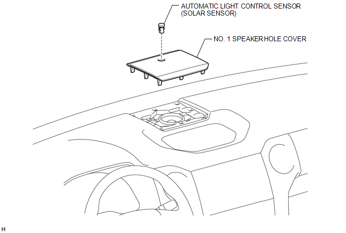
Components
COMPONENTS
ILLUSTRATION
Inspection
INSPECTION
PROCEDURE
1. INSPECT AUTOMATIC LIGHT CONTROL SENSOR (SOLAR SENSOR)
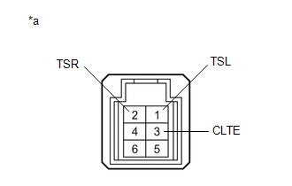
(a) Connect the positive (+) lead from the battery to terminal 6 and the negative (-) lead to terminal 3, and then measure the voltage according to the value(s) in the table below.
Standard Voltage:
Tester Connection
Condition
Specified Condition
1 (TSL) - 3 (CLTE)
Sensor subjected to electric light
0.8 to 4.3 V
Sensor covered with a cloth
0.8 V or less
2 (TSR) - 3 (CLTE)
Sensor subjected to electric light
0.8 to 4.3 V
Sensor covered with a cloth
0.8 V or less
HINT:
As the inspection light is moved away from the sensor, the voltage decreases.
Use an incandescent light for inspection. Bring it within 30 cm (11.8 in.) of the solar sensor.
Text in Illustration
*a
Component without harness connected
(Automatic Light Control Sensor (Solar Sensor))
If the result is not as specified, replace the automatic light control sensor (solar sensor).
Installation
INSTALLATION
PROCEDURE
1. INSTALL AUTOMATIC LIGHT CONTROL SENSOR (SOLAR SENSOR)
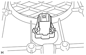
(a) Attach the 2 claws to install the automatic light control sensor (solar sensor).
2. INSTALL NO. 1 SPEAKER HOLE COVER
Removal
REMOVAL
PROCEDURE
1. REMOVE NO. 1 SPEAKER HOLE COVER
2. REMOVE AUTOMATIC LIGHT CONTROL SENSOR (SOLAR SENSOR)
(a) Detach the 2 claws and remove the automatic light control sensor (solar sensor).