Tire Pressure Warning Reset Switch
ComponentsCOMPONENTSILLUSTRATION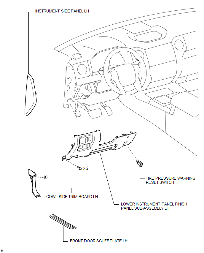
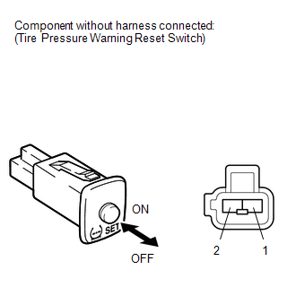
InspectionINSPECTIONPROCEDURE1. CHECK TIRE PRESSURE WARNING RESET SWITCH
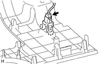
InstallationINSTALLATIONPROCEDURE1. INSTALL TIRE PRESSURE WARNING RESET SWITCH (a) Attach the 2 claws to install the tire pressure warning reset switch. (b) Connect the switch connector. 2. INSTALL LOWER INSTRUMENT PANEL FINISH PANEL SUB-ASSEMBLY LH  3. INSTALL INSTRUMENT SIDE PANEL LH 4. INSTALL COWL SIDE TRIM BOARD LH 5. INSTALL FRONT DOOR SCUFF PLATE LH RemovalREMOVALPROCEDURE1. REMOVE FRONT DOOR SCUFF PLATE LH  2. REMOVE COWL SIDE TRIM BOARD LH 3. REMOVE INSTRUMENT SIDE PANEL LH 4. REMOVE LOWER INSTRUMENT PANEL FINISH PANEL SUB-ASSEMBLY LH 5. REMOVE TIRE PRESSURE WARNING RESET SWITCH
(b) Detach the 2 claws and remove the tire pressure warning reset switch. |