Transfer Indicator Switch
ComponentsCOMPONENTSILLUSTRATION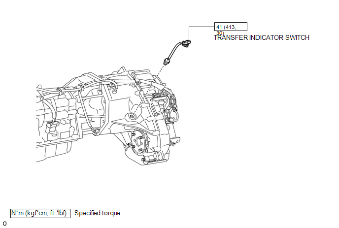
InspectionINSPECTIONPROCEDURE1. INSPECT TRANSFER INDICATOR SWITCH (a) Measure the resistance according to the value(s) in the table below. 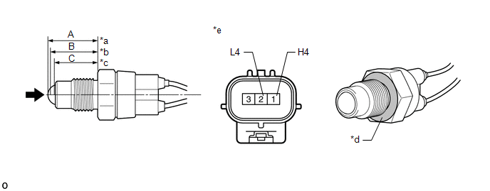
Dimension (A): 24.63 to 24.89 mm (0.970 to 0.979 in.) Dimension (B): 23.85 to 24.26 mm (0.939 to 0.955 in.) Dimension (C): 21.89 to 22.40 mm (0.862 to 0.881 in.) Text in Illustration
Standard Resistance:
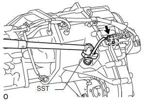
If the resistance is not as specified, replace the transfer indicator switch. HINT: The ground is the nut of the transfer indicator switch (connecting surface with the transfer case). InstallationINSTALLATIONPROCEDURE1. INSTALL TRANSFER INDICATOR SWITCH (a) Using SST, install the transfer indicator switch. SST: 09224-00010 Torque: 41 N·m {413 kgf·cm, 30 ft·lbf} NOTICE: Use the formula below to calculate special torque values for situations where SST is combined with a torque wrench (See page (b) Connect the connector and attach the clamp. 2. INSTALL FRONT NO. 2 EXHAUST PIPE ASSEMBLY
3. INSTALL FRONT PROPELLER SHAFT ASSEMBLY (See page RemovalREMOVALPROCEDURE1. REMOVE FRONT PROPELLER SHAFT ASSEMBLY (See page 2. REMOVE FRONT NO. 2 EXHAUST PIPE ASSEMBLY
3. REMOVE TRANSFER INDICATOR SWITCH
(b) Using SST, remove the transfer indicator switch. SST: 09224-00010 |

 )