Reassembly
NOTICE:
When using a vise, do not overtighten it.
PROCEDURE1. INSTALL STEERING LOCK ACTUATOR ASSEMBLY (w/ Smart Key System)
(a) Secure the steering column assembly in a vise.
(b) Temporarily install the steering lock actuator assembly to the steering column assembly with a new tapered-head bolt. NOTICE: Be sure to use a new tapered-head bolt. |
 |
(c) Tighten the tapered-head bolt until the bolt heads break off.
2. INSTALL UNLOCK WARNING SWITCH ASSEMBLY (w/o Smart Key System)
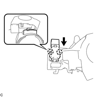
(a) Engage the 2 claws to install the unlock warning switch onto the steering column upper bracket. HINT: Slide the unlock warning switch in the direction shown by the arrow in the illustration to install it. |
 |
3. INSTALL IGNITION SWITCH LOCK CYLINDER ASSEMBLY (w/o Smart Key System)
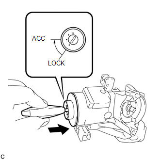
(a) Make sure that the ignition switch lock cylinder assembly is in the ACC position. |
 |
(b) Install the ignition switch lock cylinder assembly to the steering lock sub-assembly.
(c) Make sure that the ignition switch lock cylinder assembly is securely installed.
4. INSTALL SOLENOID WIRE (w/o Smart Key System)
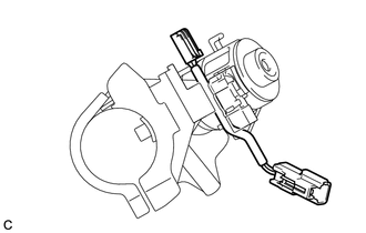
(a) Install the solenoid wire to the steering column upper bracket. |
 |
5. INSTALL KEY INTER LOCK SOLENOID (w/o Smart Key System)
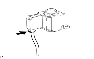
(a) Connect the solenoid wire connector to the key interlock solenoid. |
 |
(b) Install the key interlock solenoid to the steering column upper bracket with the 2 screws. |
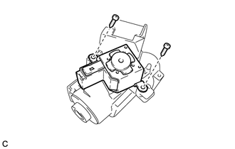 |
6. INSTALL IGNITION OR STARTER SWITCH ASSEMBLY (w/o Smart Key System)
(a) Install the ignition or starter switch assembly to the steering column upper bracket with the 2 screws. |
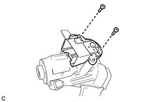 |
(b) Install the solenoid wire connector to the ignition or starter switch assembly. |
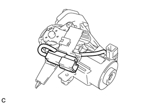 |
(c) Make sure that the solenoid wire runs securely through the gap of the steering column upper bracket as shown in the illustration. |
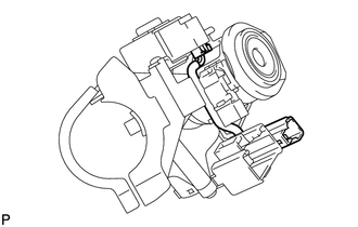 |
7. INSPECT STEERING LOCK OPERATION (w/o Smart Key System)

8. INSTALL STEERING COLUMN UPPER WITH SWITCH BRACKET ASSEMBLY (w/o Smart Key System)
(a) Secure the steering column assembly in a vise.
(b) Temporarily install the steering column upper with switch bracket assembly to the steering column assembly with a new tapered-head bolt. NOTICE: Be sure to use a new tapered-head bolt. |
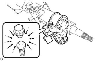 |
(c) Tighten the tapered-head bolt until the bolt heads break off.
Test yourself
A quick Toyota Venza quiz: every answer comes with an explanation and a link to the manual page.