Adaptive Chassis DCC Shock Absorber, FWD
Overview - Adaptive Chassis DCC Shock Absorber, FWD
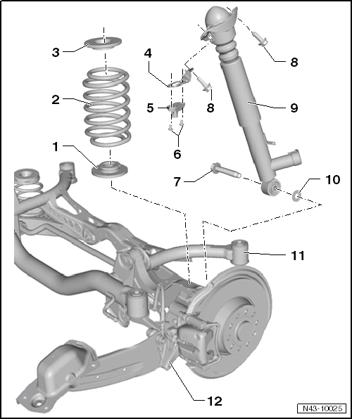
- Lower Spring Support
- Spring end rotated up to stop
- Coil Spring
- There are different suspension versions.
- Removing and installing.
- Upper Spring Support
- Bracket
- For Rear Body Acceleration Sensor -G343-
- Rear Body Acceleration Sensor -G343-
- Removing and installing.
- Note the installation position of the retainer -item 4-
- Bolt
- 5 N·m
- Always replace if removed
- Bolt
- 180 N·m
- Always replace if removedM14 x 1.5 x 85
- Bolt
- 50 N·m + 45º
- Always replace if removed
- M10 x 35
- Shock Absorber with Left and Right Rear Dampening Adjustment Valve -N338/N339-
- Removing and installing.
- There are different versions of the suspension.
- Washer
- Lower Transverse Link
- Removing and installing.
- Wheel Bearing Housing
- Removing and installing.
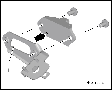
Installation Position Rear Body Acceleration Sensor -G343- on the Retainer
The tab on the retainer -1- must fit into the recess in the Rear Body Acceleration Sensor -G343--arrow-.
Rear Body Acceleration Sensor -G343-, Removing and Installing, FWD
Special tools and workshop equipment required
- Torque Wrench -VAG1410-
Removing
- Remove the wheel.
- Remove the left rear wheel housing liner.
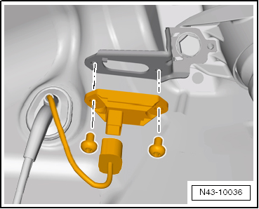
- Disconnect the connector.
- Remove the bolts and remove the Rear Body Acceleration Sensor -G343-.
Installing
Install in reverse order of removal. Note the following:
Caution
The Rear Body Acceleration Sensor -G343- must never be interchanged with the Front Body Acceleration Sensors. Refer to the Parts Catalog.
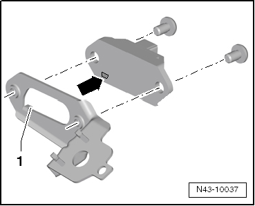
- Note the Rear Body Acceleration Sensor -G343- installation position on the retainer.
The tab on the retainer -1- must fit into the recess in the Right Front Body Acceleration Sensor -G342--arrow-.
Tightening Specifications
| Component | Tightening Specification |
| Rear Body Acceleration Sensor -G343- to the retainer | 5 N·m |
Adaptive Chassis DCC Shock Absorber, FWD, Removing and Installing
Special tools and workshop equipment required
- Torque Wrench 1332 40-200Nm -VAG1332-
Removing
- Remove the wheel.
- Remove the wheel housing liner.
For the Left Shock Absorber Only
- Remove the Left Rear Level Control System Sensor -G76- from the lower transverse link.
Continuation for Both Sides
- Remove coil spring.
- Disconnect the connector and remove the wire from the shock absorber
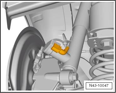
- Remove the shock absorber bolts.
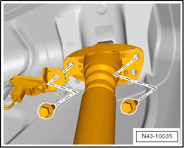
For the Left Shock Absorber Only
Remove the Rear Body Acceleration Sensor -G343- from the shock absorber mount.
Continuation for Both Sides
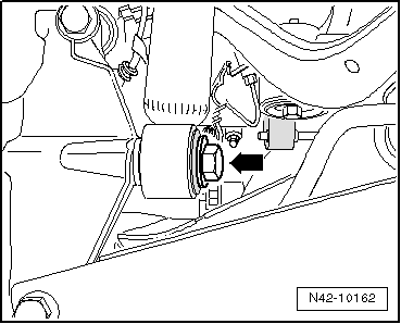
- Remove the bolt -arrow-.
- Remove the shock absorber.
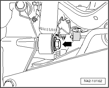
Installing
Install in reverse order of removal. Note the following:
Only bolt the shock absorber to the wheel bearing housing when the dimension "a" is reached. Note the shock absorber installation position.
The Left and Right Rear Dampening Adjustment Valve -N338/N339- must point toward the outside of the rear wheel.
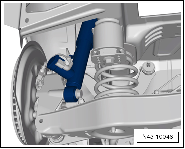
For the Left Shock Absorber Only
- Mount the Rear Body Acceleration Sensor -G343- on the shock absorber mount
- Mount the retainer on the shock absorber mount from the rear, so that the retainer tabs -1- fit into the depressions on the shock absorber mount.
- Turn the bracket forward so that it contacts the shock absorber mount.
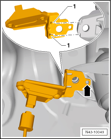
The tab -arrow- is used for adjusting the Rear Body Acceleration Sensor -G343- bracket.
Continuation for Both Sides
- Install the shock absorber and tighten the bolts.
- Tighten the bolt -arrow-.
- Connect the connector to the Left and Right Rear Dampening Adjustment Valve -N338/N339-.
- Install coil spring.
For the Left Shock Absorber Only
- Connect the Left Rear Level Control System Sensor -G76- to lower transverse link.
Continuation for Both Sides
- Install the wheel housing liner.
- Install the wheel and tighten.
Tightening Specifications
| Component | Tightening Specification |
Shock absorber to body
|
50 N·m + 45º |
Shock absorber to wheel bearing housing.
|
180 N·m |
| Left Rear Level Control System Sensor -G76- to lower transverse link | 5 N·m |
Adaptive Chassis DCC Shock Absorber, FWD, Servicing
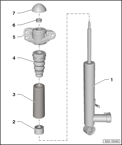
- Shock Absorber with Left and Right Rear Dampening Adjustment Valve -N338/N339-
- Removing and installing.
- Protective Cap
- Protective Pipe
- Stop Buffer
- Allocation. Refer to the Parts Catalog.
- Shock Absorber Mount
- Allocation. Refer to the Parts Catalog.
- Nut
- 25 N·m
- Always replace if removed
- M10 x 1.0
- Loosening and tightening.
- Cover
Shock Absorber, Disassembling and Assembling
Special tools and workshop equipment required
- Torque Wrench 1332 40-200Nm -VAG1332-
- Shock Absorber Set -T10001-
Loosening and Tightening Bolted Connection for Shock Absorber Mount
- Ratchet (commercially available)
- Shock Absorber Set - Extension with Counter Holder 1 -T10001/9-
- Shock Absorber Set - Reversible Ratchet -T10001/11-
- Shock Absorber Set - Socket -T10001/1-
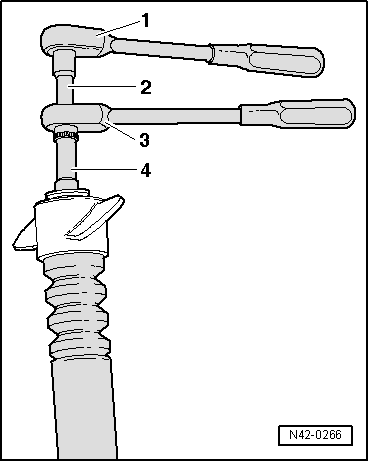
Tightening Specification
| Component | Tightening Specification |
Shock absorber mounting to shock absorber
|
25 N·m |
Test yourself
A quick Volkswagen Tiguan quiz: every answer comes with an explanation and a link to the manual page.