Window Regulator Motor, Removing and Installing

1 - Connector
- Disconnect the connector from the window regulator motor.
2 - Left Rear Window Regulator Motor -V26-
 Note
The window regulator motor can be removed or installed with the motor or door window in any position.
- Removing:
- Remove the door trim panel. Refer to → Body Interior; Rep. Gr.70; Rear Door Trim Panels; Rear Door Trim Panel, Removing and Installing.
- Remove the screws -6- and remove the window regulator motor from the window regulator.
- Installing
Install in reverse order of removal. Note the following:
- The clips-arrow- for the window regulator threaded pins must be locked into the inner door panel.
- Mount the window regulator motor on the threaded pins and tighten the screws -6-.
Note
- With the window regulator motor switches connected, switch the ignition on and run the door windows up to the stop.
- Continue holding the window regulator switch for approximately 2 seconds so the basic setting and one-touch up/down function are activated.
3 - Threaded Pin
4 - Window Regulator
5 - Bolt
- Tightening specification. Refer to -item 8-.
Window Regulator, Removing and Installing
Removing
- Remove the door window. Refer to → Chapter "Front Door Window, Removing and Installing".
- Remove the power window motor. Refer to → Chapter "Window Regulator Motor, Removing and Installing".
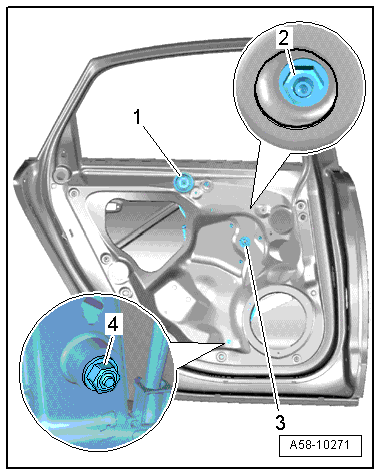
- Remove the retainer -arrows- over the threaded pin -1- for the window regulator, for example, with an 11 mm socket .
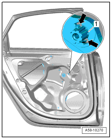
- Pry out the plug -1-.
- Loosen the nuts -2- at the top only, remove the nut -4- at the bottom, Counterhold the threaded pin -2- for adjusting the door window while doing this.
- Remove the window regulator -3- back out of the opening in the inner door panel.
Installing
Install in reverse order of removal. Note the following:
- The clips -arrows- for the window regulator motor threaded pins -1- must be engaged in the inner door panel.
Closing Assist Motor, Removing and Installing
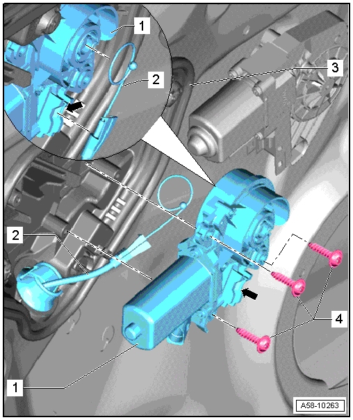
1 - Left Rear Closing Assist Motor -V307-
- Removing
- Remove the door trim panel. Refer to → Body Interior; Rep. Gr.70; Rear Door Trim Panels; Rear Door Trim Panel, Removing and Installing.
- Disconnect the connector from the motor.
- Remove the bolts from the motor.
- Guide the release cable out of the cable winder.
- Installing
- When installing, first insert the cable end into the cable winder.
- Place the cable 360º inside the groove in the cable winder.
- Install the cable -arrows- into the motor.
- Tighten the motor.
2 - Release Cable
3 - Inner Door Panel Cover
4 - Bolt
- 3 N·m
Door Inner Cover, Removing and Installing
Note
The illustration shows the cover for a vehicle with close assist and locks that have to be released before removing.

1 - Cover
Vehicle without Close Assist
- Remove the door trim panel. Refer to → Body Interior; Rep. Gr.70; Rear Door Trim Panels; Rear Door Trim Panel, Removing and Installing.
- Remove the electric wires from the clamps -5-.
- When removing the cover, always start at the top.
Vehicle with Closing Aid
- Remove the door trim panel. Refer to → Body Interior; Rep. Gr.70; Rear Door Trim Panels; Rear Door Trim Panel, Removing and Installing.
- Disconnect the voltage supply to the closing assist motor
- Open the releases (quantity: 5) turning them to the left and remove the cover from the inner door panel.
2 - Grommet with Cable
 Caution
Do not bend the cables when installing them.
- When installing, it must fit correctly -arrows-.
3 - Inside Door Release Mechanism Release
4 - Release (Quantity: 5)
- Turn the cover to the left to unlock it.
- Must click into the place when being installed.
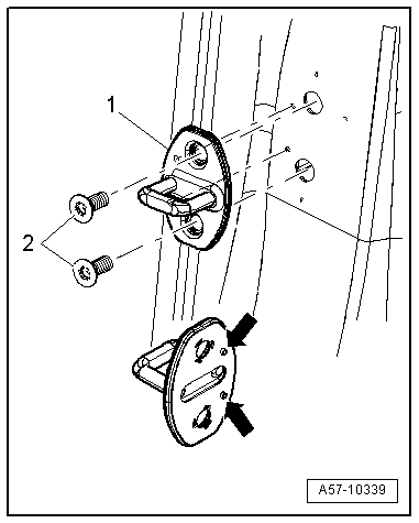
Catch, Removing and Installing
Removing
- Remove the bolts -2- and the catch -1-.
Installing
Install in reverse order of removal.
Note
- The striker pin backing must be position with the pins -arrows- exactly in the hole.
- The striker pins must be sheared off cleanly after sliding the striker pin.
- If a new part is being installed, then remove the sheared off pins from the striker pin.
- Adjust the catch. Refer to → Chapter "Catch, Adjusting".