Description and Operation - About This Manual
Introduction
For additional information, refer to: Health and Safety Precautions (100-00 General Information, Description and Operation).
This manual describes and provides the repair procedures specified by Ford Motor Company for the vehicle. Important health and safety precautions are included. Anyone who deviates from these instructions risks compromising personal safety or the integrity of the vehicle.
SECTION CONTENTS
This manual is divided into groups, each containing sections numbered according to the component number. Section contents may include:
- Specifications
- Fluid capacities, component specifications and torque values not described in other procedures
- Description and Operation
- System overview, component location and system operation
- Diagnosis and Testing
- Symptom charts, DTC charts and diagnostic tests
- Refer to diagnosis and testing information in this document.
- General Procedures
- Service adjustments, electronic programming and other special procedures
- Removal and Installation
- Removal and Installation Instructions for components
- Removal
- Component removal instructions
- Installation
- Component installation instructions
- Disassembly and Assembly
- Disassembly and assembly instructions for components
- Disassembly and Assembly of Assemblies
- Disassembly and Assembly Instructions
IMPORTANT INFORMATION
Section 100-00 General Information contains the following important information (including this document):
- Critical Health and Safety Precautions - service precautions that apply to the entire manual.
For additional information, refer to: Health and Safety Precautions (100-00 General Information, Description and Operation). - Symbol Glossary - definitions of the action indicated by each symbol.
For additional information, refer to: Symbol Glossary (100-00 General Information, Description and Operation). - Diagnostic Methods - supplementary diagnostic information.
For additional information, refer to: Diagnostic Methods (100-00 General Information, Description and Operation).
Warnings, Notices and Notes
WARNINGS
WARNINGS provide information to avoid injury and to ensure that service actions on critical safety systems are performed correctly. Warnings that apply to the entire system or to a section of the service manual are located in Section 100-00 General Information, Description and Operation, Health and Safety Precautions.
For additional information, refer to: Health and Safety Precautions (100-00 General Information, Description and Operation).
NOTICES (in some publications, CAUTIONS)
Notices contain information to help avoid damage to the vehicle or its components.
NOTES
Notes contain important information for a complete and effective repair.
Warnings, Notices or Notes that apply to the entire procedure are placed at the beginning of the procedure. Warnings, Notices or Notes that apply to a single step are placed at the beginning of that step. Those that apply to a group of steps are placed at the first step that requires them.
Safety Systems
Repair of a vehicle safety-related system is accomplished only by replacing the failed component(s), unless otherwise specified in the procedure. Do not attempt to repair a component of a system that affects vehicle safety.
If directed during assembly of system components, lubricate all seals only with the specified material. Failure to follow this instruction may result in leaks and loss of sealing.
Specific Chemicals or Materials
This manual specifies chemicals or materials that must be used to properly complete a service procedure or diagnostic step. If the specific material is not available, a replacement material meeting the same specifications may be used. Ford has not evaluated third-party products for compliance with environmental, health or safety regulations and is not responsible for their use. Use of third-party products is at the user's own risk. In addition, such products may cause reduced performance, premature failures and/or damage to vehicle components. All chemicals or materials used to service the vehicle must be checked for compliance with local environmental and health regulations.
LH and RH Designations
All LH and RH designations are determined from the driver's seat position, facing forward.
Determining Vehicle Left and Right Side
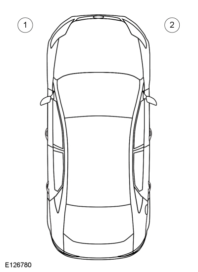
| Item | Part Number | Description |
|---|---|---|
| 1 | — | LH (Left-Hand) |
| 2 | — | RH (Right-Hand) |
All engine LH and RH designations are determined from the flywheel end toward the crankshaft pulley end.
Determining Engine Left and Right Side
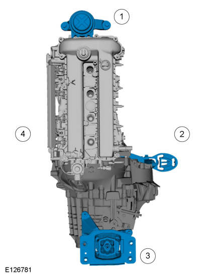
| Item | Part Number | Description |
|---|---|---|
| 1 | — | Front |
| 2 | — | RH (Right-Hand) |
| 3 | — | Rear |
| 4 | — | LH (Left-Hand) |
Standard Practices
The following practices apply unless otherwise specified in the procedure:
FASTENERS
- Reuse standard fasteners.
- Replace prevailing torque fasteners.
- Examples of prevailing torque fasteners or mechanical locking features (locking features highlighted in yellow) are shown in the illustration.
Examples of Prevailing Torque Nuts and Bolts
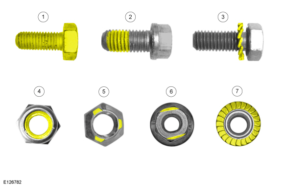
| Item | Part Number | Description |
|---|---|---|
| 1 | — | Fully coated prevailing torque bolt |
| 2 | — | Partially coated prevailing torque bolt |
| 3 | — | Prevailing torque bolt with locking washer |
| 4 | — | Prevailing torque nut with plastic insert |
| 5 | — | Prevailing torque nut with deformed thread (3 indentations) |
| 6 | — | Prevailing torque nut with deformed thread (oval shape) |
| 7 | — | Prevailing torque nut with integral locking ring |
THREAD-FORMING FASTENERS
The following is a general description of best practices to follow when handling thread-forming fasteners and mating components.
Hand Torque Application
Hand tools are required to install thread-forming fasteners. DO NOT use power tools, as they may cause excessive torque or thread breakage. If the fastener is overtightened, the joint may fail.
Reverse Hand-Start Fasteners
To avoid cross-threading the existing threads when replacing fasteners, start by manually inserting the new fastener and turning it counterclockwise. This reverse rotation allows the fastener to engage the existing threads and ensures that the fastener does not cross-thread when re-engaging. Once the fastener is engaged in the existing threads, turn the fastener by hand until it is snug.
Risks of Over-Torquing
Refer to the Torque Sequence for thread-forming fasteners in the Workshop Manual and follow the torque specification as specified. Make sure the fastener is fully seated against the mating component with no gap during reassembly.
Corrosion
During fastener replacement, inspect the fastener and mating component for signs of rust or other corrosion. If corrosion is found, replace the corroded components with new components.
Stripped Threads
If the internal (mating component) thread or external (fastener) thread appears bare or scratched, replace the fastener and mating component. During tightening, if the minimum torque is not reached, the internal thread on the mating component may be stripped. Remove the fastener to inspect and replace the mating component if stripped threads are found.
Face Seals
When replacing fasteners, inspect the mating surface for debris, damage, wear or abrasion, and replace any seals or gaskets if damage is found.
SEALS AND GASKETS
Replace seals and gaskets unless otherwise specified in the procedure.
EXTERIOR TRIM PARTS
Replace exterior trim parts that are secured with adhesive or adhesive tape unless otherwise specified in the procedure.
Mechanical Procedures
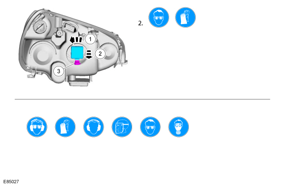
Illustrations in this manual can be used in place of written step-by-step instructions. Color coding (see the color coding illustration) is used to identify the required step or steps. Service action icons can be used to add information about the required actions.
For additional information, refer to: Symbol Glossary (100-00 General Information, Description and Operation).
Color Coding Illustration
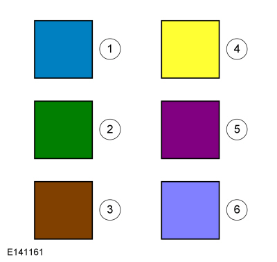
| Item | Part Number | Description |
|---|---|---|
| 1 | — | Blue - Target or primary component to be removed/installed (or disassembled/assembled). |
| 2 | — | Green - Components that must be removed before or installed after the target/primary component. |
| 3 | — | Brown - Components that must be removed before or installed after the target/primary component. |
| 4 | — | Yellow - Components that must be moved aside for access, but not removed. Also highlights areas to be inspected or adjusted. |
| 5 | — | Purple - Electrical connectors and fasteners such as nuts, bolts, clamps or brackets that must be: disconnected, attached, loosened, moved, removed or installed. |
| 6 | — | Light Blue - Special tool(s), general equipment or common tools used in an unusual way. |
Other Color Markings
- Alternating blue and white
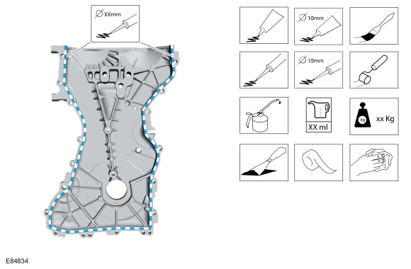
- Areas where chemicals, adhesive or sealant are applied
- Red
- Sectioned or cut-away areas
- Gray
- Background components are shown for location information
ILLUSTRATION TASK SEQUENCE
Components that must be removed or installed in a specific sequence are shown with a numbered callout. Any associated step text is numbered accordingly.
Example of a simple procedure showing color coding and task sequence.
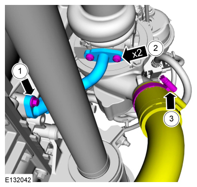
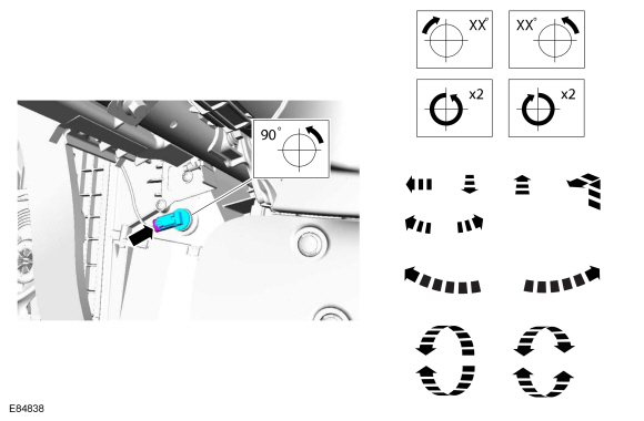
Black arrows are used to draw attention to components (usually fasteners). Arrows with a multiplier (here x2) indicate the same number of fasteners or items. Callouts (numbers inside circles) show the required sequence or tightening torque.
In the illustration, callouts indicate the removal sequence, which is reversed for installation . A yellow hose indicates that it should be moved aside (not removed). Two identical purple fasteners are indicated by the arrow x2. Fasteners in this illustration require different torques (same torque for the x2 fasteners), so numbered callouts are used to identify them with torque values in the corresponding step text. The purple hose clamp is another fastener that must be removed.
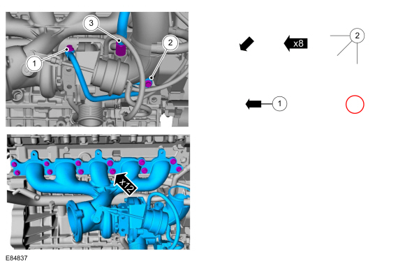
Examples of fastener removal sequence and identical service operation for 12 fasteners. Other possible symbols are shown on the right.
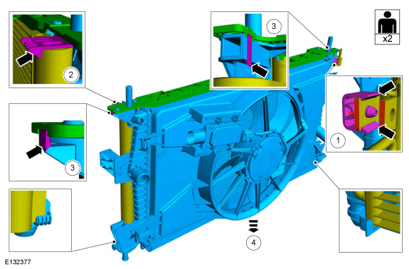
Example of fastener sequence information requiring two people for service
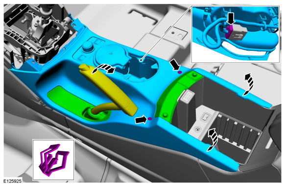
HIDDEN DETAILS
Separate component blocks or transparent components may be used to show hidden items in the illustration.
Example of hidden fastener information
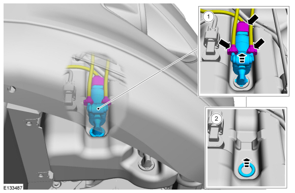
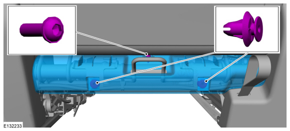
SERVICE ACTION ICONS
Service action icons can be used to add information about the required action.
For additional information, refer to: Symbol Glossary (100-00 General Information, Description and Operation).
Location symbols show the location of a component or system on the vehicle.
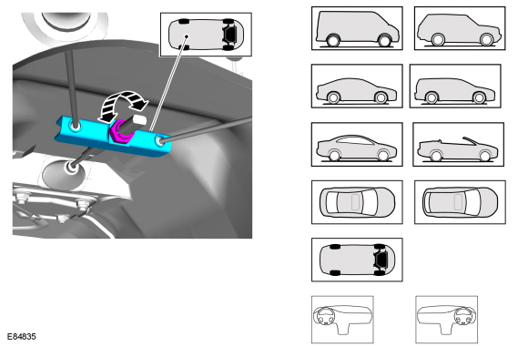
Example of service action icons indicating highlighted components.
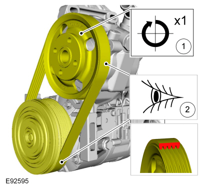
Movement arrows and service action icons show three-dimensional or rotational movements.
Instruction symbols are used to indicate application of sealant, lubricant, grease, tape or cleaner to a component.
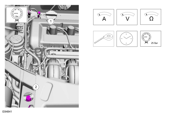
Measurement symbols provide information required to perform a specific measurement. These symbols may include specific values.
SPECIAL TOOLS, POWER TOOLS, GENERAL EQUIPMENT, MATERIALS AND TORQUE VALUES
Commercially available power tools, hand tools and general equipment are used in service together with Ford special tools. Use of power tools is permitted during removal or disassembly procedures unless otherwise specified in the service procedure. Do not use power tools during assembly or installation, except for wheel installation. The use of a pneumatic impact wrench in combination with a torque stick is permitted. Follow the torque stick manufacturer's recommendations when tightening wheel nuts.
When Ford special tools are required for a procedure, the tool and tool number are shown in the illustration. Special tool numbers, general equipment, materials or torque values for a procedure step are shown in the text steps.
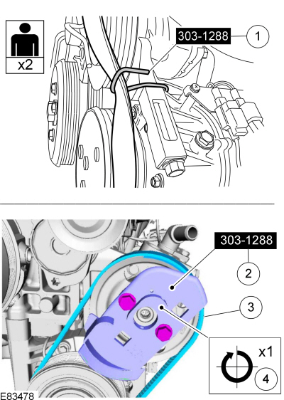
Example of a special service tool and symbol used to hold the transmission gear selector in the required gear position. Other possible symbols are shown on the right.
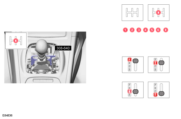
Example of two illustrations used together with sequence steps, service action icons and special service tools
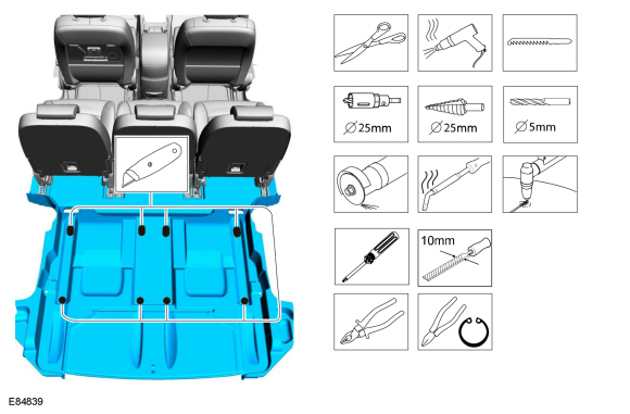
Tool symbols identify the use of standard tools. Tool size may be specified.
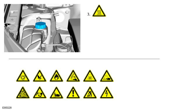
HEALTH AND SAFETY SYMBOLS
Some procedures may contain health and safety symbols related to a specific service action.
For additional information, refer to: Symbol Glossary (100-00 General Information, Description and Operation).
Always read and understand all health and safety precautions contained in Section 100-00 before starting any procedure. For additional information, refer to: Health and Safety Precautions (100-00 General Information, Description and Operation).
ISO warning symbols may be used to indicate potential hazards.
These symbols prohibit various hazardous actions.
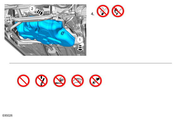
These symbols indicate the use of personal protective equipment.
Diagnosis and Testing Information
DIAGNOSTIC AND TESTING ELEMENTS
Diagnostics and testing may include:
- Preliminary Inspection
- In older manuals, Inspection and Verification
- Symptom Chart
- Diagnostic Trouble Code Chart
- Pinpoint Tests
- Component Tests
Some diagnostics may be contained in Symptom-Based Diagnostics. Some engine performance and emissions diagnostics may be located in a separate PCM/ED published manual.
MODULE NAMES CORRESPOND TO THE DIAGNOSTIC SCAN TOOL
Module names and PID names in this manual correspond to the Ford diagnostic scan tool: IDS or FDRS.
The same diagnostic scan tool module name appears in some DTC definitions (for example, U024B Lost Communication With Seat Control Module "G").
DESCRIPTIVE MODULE NAMES
A descriptive name is sometimes added to the diagnostic scan tool name to clarify the function of the module. The descriptive name is followed by the diagnostic scan tool abbreviation in brackets.
- Example: "Driver Seat Active Motion Module [SCMG]".
- Driver Seat Active Motion Module is the descriptive name added to explain the function of SCMG.
- The abbreviation SCMG is used by the diagnostic scan tool and is defined as "Seat Control Module G".
Test yourself
A quick Ford Escape quiz: every answer comes with an explanation and a link to the manual page.