Body Electrical System
Smart Key Unit Repair Procedures
In this manual: Body Electrical System
63steps
~378min
4/5difficulty
Done 0 of 63
Removal
Smart Key Unit- Disconnect the negative (-) battery terminal.
- Remove the glove box housing. (Refer to Group BD - "Crash Pad")
- Disconnect the smart key unit connector (A), loosen the smart key unit mounting bolts, and remove the smart key unit (B).
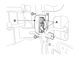
- Disconnect the negative (-) battery terminal.
- Remove the glove box housing. (Refer to Group BD - "Crash Pad")
- Remove the ventilation duct cover in front of the passenger seat. (Refer to Group BD - "Crash Pad")
- Loosen the mounting nut (B), disconnect the connector (A), and remove the receiver (C).
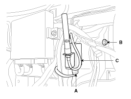
- Disconnect the negative (-) battery terminal.
- Remove the front seat heater switch assembly. (Refer to Group BE - "Seat Heater")
- Loosen the antenna nuts (2EA) and disconnect the connector (B), then remove interior antenna 1 (A).
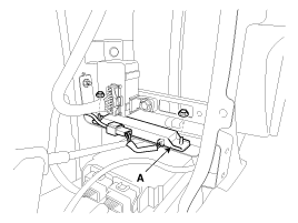
Release the connector lock (A) as shown by the arrow, then press the lock. When installing, make sure the connector is fully locked.
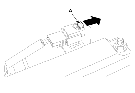
- Disconnect the negative (-) battery terminal.
- Remove the rear floor console panel (A) using the appropriate tool.
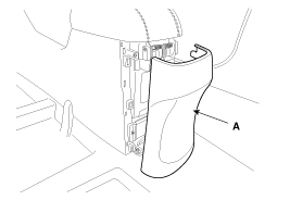
Be careful not to damage or scratch the rear floor console panel and related parts. Be careful not to damage the clip when removing the rear floor console panel. - Loosen the antenna nuts (2EA) and disconnect the connector, then remove interior antenna 2 (A).
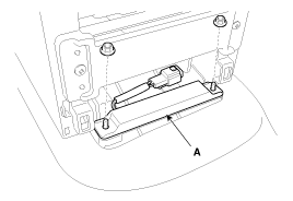
Release the connector lock (A) as shown by the arrow, then press the lock. When installing, make sure the connector is fully locked. - Disconnect the negative (-) battery terminal.
- After loosening the mounting bolts, remove the rear seat assembly. (Refer to Group BD - "Rear Seat")
- Loosen the antenna nuts (2EA) and disconnect the connector (A), then remove interior antenna 3 (B).
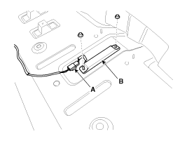
Release the connector lock (A) as shown by the arrow, then press the lock. When installing, make sure the connector is fully locked. - Disconnect the negative (-) battery terminal.
- Raise the vehicle using a lift. (Refer to Group GI - "Jacking and Lifting Points")
- Disconnect the antenna connector (A) in the center of the rear bumper.
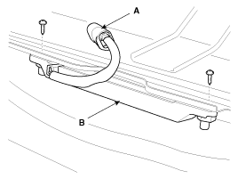
- After loosening the nuts (2EA), remove the outside bumper antenna (B).
- Disconnect the negative (-) battery terminal.
- Remove the front left fender. (Refer to Group BD - "Fender")
- Disconnect the connectors, then remove the buzzer (A).
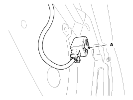
- Disconnect the negative (-) battery terminal.
- Disconnect the connector after removing the door trim. (Refer to Group BD - "Front Door")
- Loosen the mounting bolt and remove the key holder (A).
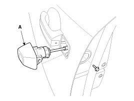
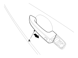
- Remove the outside handle (A) by sliding it rearward.
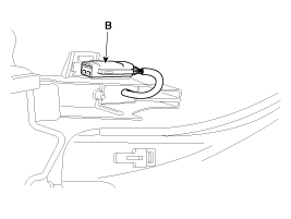
- Disconnect the outside handle connector (B).
- Disconnect the negative (-) battery terminal.
- Remove the rear door trim. (Refer to Group BD - "Rear Door Trim")
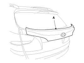
- Disconnect the connector. Loosen the mounting nuts of the rear liftgate garnish (13EA), then remove the garnish (A).
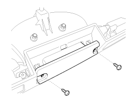
- Remove the outside handle (A) after loosening the outside handle mounting screws.
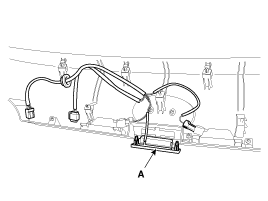
- Disconnect the other wiring connectors connected to the outside handle, then remove the liftgate switch assembly (A).
Inspection
Smart Key Unit- Refer to Group BE - Inspection/Self-Diagnosis Using the Diagnostic Tool.
- Refer to Group BE - Inspection/Self-Diagnosis Using the Diagnostic Tool.
- Refer to Group BE - Inspection/Self-Diagnosis Using the Diagnostic Tool.
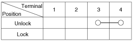
- Check the circuit continuity between the terminals of the rear liftgate lock.
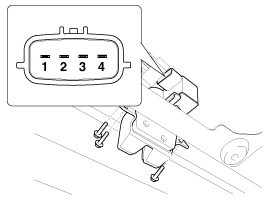
- If continuity is not as specified, inspect the switch.
Installation
Smart Key Unit- Install the smart key unit.
- Install the smart key unit mounting bolt and nut, then connect the connector.
- Install the glove box.
- Connect the negative (-) battery terminal and check the smart key system.
- Install the radio frequency receiver.
- Install the glove box housing and the ventilation duct cover.
- Connect the negative (-) battery terminal and check the smart key system.
- Install the interior 1 antenna.
- Install the front seat heater switch assembly.
- Connect the negative (-) battery terminal and check the smart key system.
- Install the interior 2 antenna.
- Install the rear floor console cover after connecting the connector.
- Connect the negative (-) battery terminal and check the smart key system.
- Install interior antenna 3.
- Install the rear seat assembly.
- Connect the negative (-) battery terminal and check the smart key system.
- Install the bumper exterior antenna.
- Connect the negative (-) battery terminal and check the smart key system.
- Install the buzzer.
- Install the front left fender.
- Connect the negative (-) battery terminal and check the smart key system.
- Install the outside handle.
- Install the door trim panel.
- Connect the negative (-) battery terminal and check the smart key system.
- Install the liftgate switch.
- Install the rear door garnish.
- Install the rear door trim.
- Connect the negative (-) battery terminal and check the smart key system.
Test yourself
A quick Hyundai Tucson LM quiz: every answer comes with an explanation and a link to the manual page.
Was this page helpful?