Body Electrical System
Smart Key Unit Repair Procedures
In this manual: Body Electrical System
64steps
~384min
4/5difficulty
Done 0 of 64
Inspection
Smart Key Unit- Refer to the BE group - Inspection/Self-Diagnosis using GDS.
- Refer to the BE group - Inspection/Self-Diagnosis using GDS.
- Refer to the BE group - Inspection/Self-Diagnosis using GDS.
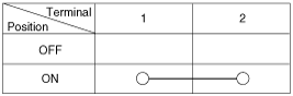
- Check the circuit continuity between the terminals of the trunk lid open switch.
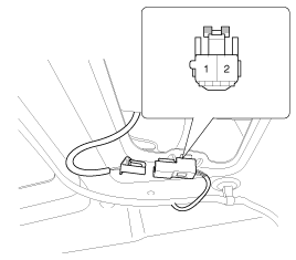
- If continuity is not as specified, inspect the switch.
Removal
|
- Disconnect the negative (-) battery terminal.
- Remove the glove box. (Refer to Group BD - "Crash Pad")
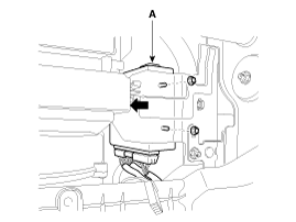
- Remove the smart key unit (A) by disconnecting the connector and loosening the mounting nuts (2 pcs).
- Remove the smart key unit (A) with bracket (B) after loosening the mounting nuts and shear bolts (C). [CANADA]
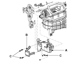
Do not reuse shear bolts. When installing a new smart key unit, tighten the shear bolts until the head breaks off.
|
- Disconnect the negative (-) battery terminal.
- Remove the glove box. (Refer to Group BD - "Crash Pad")
- Remove the radio frequency receiver (A) by loosening the mounting nut (1 pc) and disconnecting the connector.
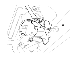
|
- Disconnect the negative (-) battery terminal.
- Remove the heater control unit (A) by removing the screws. (Refer to Group BD - "Crash Pad")
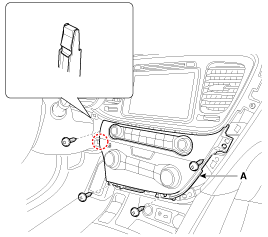
- Remove the interior antenna 1 (A) by disconnecting the connector and loosening the mounting nuts (2EA).
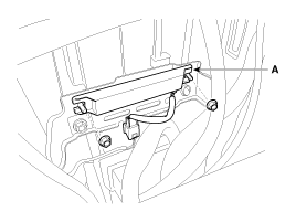
- Disconnect the negative (-) battery terminal.
- Remove the center console rear cover (A).
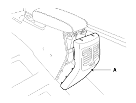
Be careful not to damage or scratch the console rear cover and related parts. Apply protective tape to the console rear cover and related parts.
- Disconnect the interior antenna 2 connector located at the rear of the console, then remove interior antenna 2 (A) after loosening the screws (2 pcs).
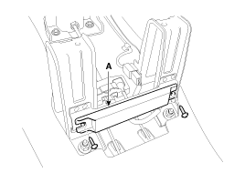
- Disconnect the negative (-) battery terminal.
- Remove the luggage compartment side trim. (Refer to Group BD - "Interior Trim")
- Disconnect the main antenna connector (A) and remove the main antenna (B) after loosening the nut (2EA).
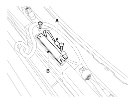
- Disconnect the negative (-) battery terminal.
- Remove the rear bumper. (Refer to Group BD - "Rear Bumper")
- Disconnect the antenna connector (B) and remove the exterior bumper antenna (A) after loosening the screws (2 pcs).
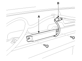
- Disconnect the negative (-) battery terminal.
- Remove the left side wheel guard.
- Remove the external buzzer (A) after disconnecting the connector.
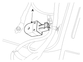
- Disconnect the negative (-) battery terminal.
- Remove the front door module. (Refer to BD group - "Front Door")
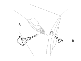
- Remove the hole plug (B).
- Loosen the mounting bolt, then remove the outside handle cover (A).
Tightening torque: 0.7 ~ 0.5 N·m
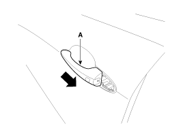
- Remove the outside handle (A) by sliding it rearward.
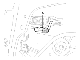
- Disconnect the outside handle connector (A).
- Disconnect the negative (-) battery terminal.
- Remove the tailgate trim. (Refer to Group BD - "Tailgate")
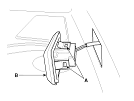
- Disconnect the trunk lid open switch connector (A).
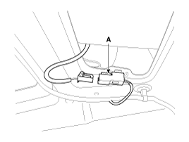
- Remove the tailgate open switch (A) from the trim by pressing the clips (B).
Installation
Smart Key Unit- Install the smart key unit.
- Install the smart key unit mounting nuts and bolts, and connector.
- Install the glove box housing.
- Install the glove box.
- Connect the negative (-) battery terminal and check the smart key system.
- Install the radio frequency receiver.
- Install the glove box housing.
- Install the glove box.
- Connect the negative (-) battery terminal and check the smart key system.
- Install the interior 1 antenna.
- Install the heater control unit.
- Connect the negative (-) battery terminal and check the smart key system.
- Install the interior 2 antenna.
- Install the console rear cover after connecting the connector.
- Connect the negative (-) battery terminal and check the smart key system.
- Install the main antenna.
- Install the liftgate trim.
- Connect the negative (-) battery terminal and check the smart key system.
- Install the bumper exterior antenna.
- Install the rear bumper.
- Connect the negative (-) battery terminal and check the smart key system.
- Install the buzzer.
- Install the left side wheel guard.
- Connect the negative (-) battery terminal and check the smart key system.
- Install the trunk lid open switch.
- Install the liftgate trim.
- Connect the negative (-) battery terminal and check the smart key system.
- Install the outside handle.
- Install the door trim panel.
- Connect the negative (-) battery terminal and check the smart key system.
Test yourself
A quick Kia Optima Hybrid Owner's Manual quiz: every answer comes with an explanation and a link to the manual page.
Was this page helpful?