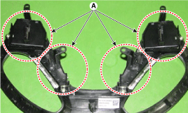
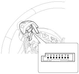
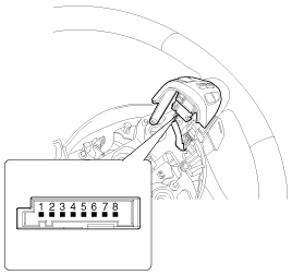
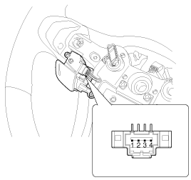
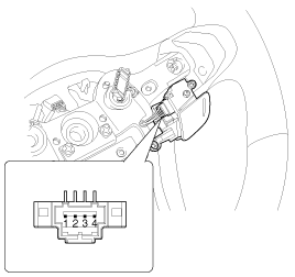
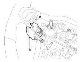
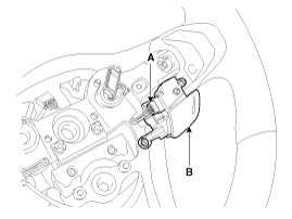
Check the resistance between the terminals of the audio remote control switch (A) in each switch position.[Audio]
Switch
Connector Terminal
Resistance (±5%)
Seek
2-7
430 Ω
Close
2-7
1.1 kΩ
Mode
2-7
2.11 kΩ
Mute
2-7
3.11 kΩ
Volume Up
2-7
4.61 kΩ
Volume Down
2-7
6.81 kΩ
[Call + Voice]
Switch
Connector Terminal
Resistance (±5%)
Voice
2-5
3.9 kΩ
Release
2-5
12.1 kΩ
Call
2-5
34.1 kΩ
[Cruise + Flex]
Switch
Connector Terminal
Resistance (±5%)
Cancel
2-7
180 Ω
SETUP
2-7
330 Ω
Summary
2-7
550 Ω
Cruise
2-7
880 Ω
S/Limit
2-7
1.44 kΩ
Flex Control
4-7
0 ohms
[Travel]
Switch
Connector Terminal
Resistance (±5%)
Trip
2-5
330 Ω
STEP
2-5
550 Ω
TRIP DOWN
2-5
880 Ω
Type B
Check the resistance between the connector terminals of the audio remote control switch (A) in each switch position. [Audio/Bluetooth/Drive Mode][Trip + Cruise][Voice Recognition][ECO Mode / Travel / Drive][Audio/Bluetooth/Drive Mode]
Switch
Connector Terminal
Resistance (±5%)
Seek
2-7
430 Ω
Seek down
2-7
1.11 kΩ
Mode
2-7
2.11 kΩ
Mute
2-7
3.11 kΩ
Volume Up
2-7
4.61 kΩ
Volume Down
2-7
6.81 kΩ
Release
2-7
18.91 kΩ
Call
2-7
40.91 kΩ
Drive Mode
4-6
4.1 kΩ
[Travel]
Switch
Connector Terminal
Resistance (±5%)
Trip
3-7
330 Ω
STEP
3-7
550 Ω
TRIP DOWN
3-7
880 Ω
Select
3-7
1.44 kΩ
[Voice Recognition]
Switch
Connector Terminal
Resistance (±5%)
Voice
Audio Terminal 2 and Voice Recognition 3
10.71 kΩ
[ECO Mode / Travel / Drive]
Switch
Connector Terminal
Resistance (±5%)
Trip
2-4
330 Ω
STEP
2-4
550 Ω
TRIP DOWN
2-4
880 Ω
Select
2-4
1.44 kΩ
ECO
2-4
2.54 kΩ
Drive Mode
2-4
5.54 kΩ
Removal
Enter
Disconnect the negative (-) battery terminal.
Remove the driver airbag module. (Refer to Restraint System - "Driver Airbag Module (DAB) and Clock Spring")
Remove the steering wheel. (Refer to Steering System - "Steering Column and Shaft")
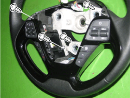
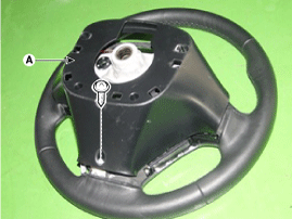
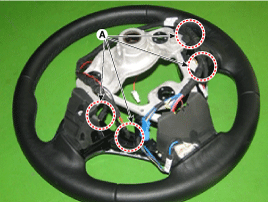
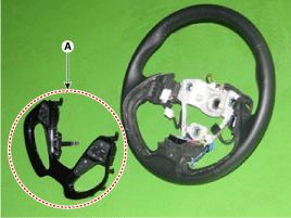
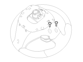
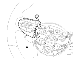
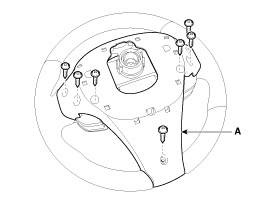
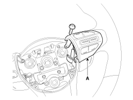
Remove the steering wheel cover (A) after loosening the screws.
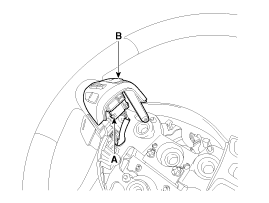
Disconnect the remote control switch connector on the steering wheel (A).
Disconnect the steering wheel remote control switch assembly (A).
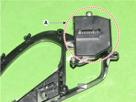
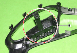
Remove the steering wheel remote control switch (A) and (B) after loosening the screws.
Type B
[Upper Remote Control Switch on Steering Wheel]
Disconnect the negative (-) battery terminal.
Remove the driver airbag module. (Refer to Group RT)
Remove the steering wheel. (Refer to Group ST - "Steering Column and Shaft")
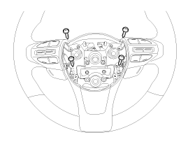
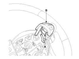
Loosen the mounting screws on the steering wheel rear cover.
Detach the upper left steering wheel remote control switch (A) after loosening the mounting screw.
Remove the upper left steering wheel remote control switch (A) after disconnecting the connector.
Disconnect the negative (-) battery terminal.
Remove the driver airbag module. (Refer to Group RT)
Remove the steering wheel. (Refer to Group ST - "Steering Column and Shaft")
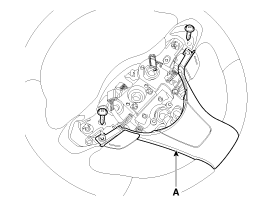
Loosen the mounting screws on the steering wheel front cover.
Remove the upper left steering wheel cover (A) after loosening the mounting screws.
Detach the upper steering wheel remote control switch (A) after loosening the mounting screw. [Left][RH]
Remove the upper steering wheel remote control switch (A) after disconnecting the connector. [Left][RH]
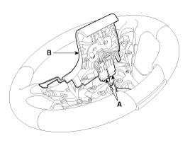
Remove the steering wheel cover (A) after loosening the mounting screws from the steering wheel front cover.
Remove the steering wheel front cover (B) after disconnecting the connector (A).
Remove the lower steering wheel remote control switch (B) after disconnecting the connector (A). [Left][RH]
[Lower Remote Control Switch on Steering Wheel]
Installation
Enter
Assemble the steering wheel remote control switch after connecting the connector.
Install the steering wheel.
Install the driver airbag module.
Type B
[Upper Remote Control Switch on Steering Wheel]
Install the upper left steering wheel remote control switch and the rear steering wheel cover.
Install the steering wheel.
Connect the steering wheel remote control switch connector and the airbag connectors.
Install the driver airbag module.
Connect the negative (-) battery terminal.
Install the lower/upper steering wheel remote control switch and the front/rear steering wheel cover.
Install the steering wheel.
Connect the steering wheel remote control switch connector and the airbag connectors.
Install the driver airbag module.
Connect the negative (-) battery terminal.
[Lower Remote Control Switch on Steering Wheel]
?
Test yourself
A quick Kia Cee'd quiz: every answer comes with an explanation and a link to the manual page.