Blind Spot Monitoring (Bsm) Control Module Inspection
1. Disconnect the negative battery cable.
2. Remove the rear combination light..
3. Remove the rear bumper..
4. Connect the negative battery cable..
5. Measure the voltage at each terminal is as indicated in the Terminal Voltage Tables.
If the voltage or continuity is not as specified in the Terminal Voltage Table, inspect the parts under “Inspection item (s)”.
If the system does not operate normally even though the related wiring harness and short cord are normal, replace the BSM control module.
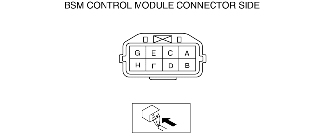
BSM control module (LH)
Terminal |
Signal |
Connected to |
Measurement condition |
Voltage (V) |
Inspection item (s) |
|
A |
Ground |
Body ground |
Under any condition |
1.0 or less |
|
|
B |
Power supply |
METER 15 A fuse |
Switch the ignition ON |
B+ |
|
|
Switch the ignition OFF (LOCK) |
1.0 or less |
|||||
D |
BSM indicator light (LH) signal |
BSM indicator light (LH) |
Switch the ignition to ON |
LED off |
1.0 or less |
|
LED on |
B+ |
|||||
E |
Ground |
Body ground |
Under any condition |
1.0 or less |
|
|
G |
CAN_L |
CAN system related module |
Because this terminal is for communication, good/no good judgment by terminal voltage is not possible. |
|||
H |
CAN_H |
CAN system related module |
Because this terminal is for communication, good/no good judgment by terminal voltage is not possible. |
|||
BSM control module (RH)
Terminal |
Signal |
Connected to |
Measurement condition |
Voltage (V) |
Inspection item (s) |
|
A |
Ground |
Body ground |
Under any condition |
1.0 or less |
|
|
B |
Power supply |
METER 15 A fuse |
Switch the ignition ON |
B+ |
|
|
Switch the ignition OFF (LOCK) |
1.0 or less |
|||||
D |
BSM indicator light (RH) signal |
BSM indicator light (RH) |
Switch the ignition to ON |
LED off |
1.0 or less |
|
LED on |
B+ |
|||||
E |
BSM OFF switch signal |
BSM OFF switch |
Switch the ignition to ON |
BSM switch pressed |
1.0 or less |
|
BSM switch not pressed |
B+ |
|||||
G |
CAN_L |
CAN system related module |
Because this terminal is for communication, good/no good judgment by terminal voltage is not possible. |
|||
H |
CAN_H |
CAN system related module |
Because this terminal is for communication, good/no good judgment by terminal voltage is not possible. |
|||
Test yourself
A quick Mazda 3 quiz: every answer comes with an explanation and a link to the manual page.