Front Propeller Shaft
Exploded View
REMOVAL
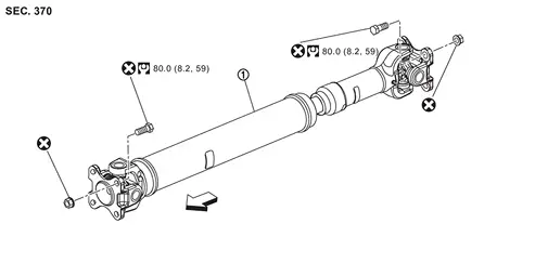
 |
Propeller shaft assembly | ||||
| : vehicle front | |||||
 : N·m (kg-m, ft-lb) |
|||||
 : Always replace after every disassembly. |
|||||
DISASSEMBLY
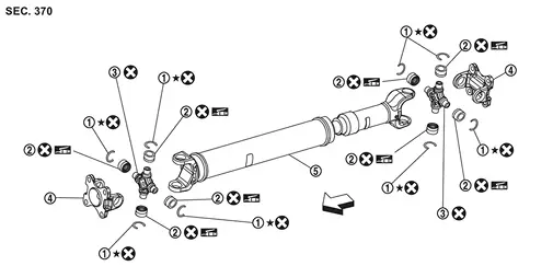
|
Snap ring |  |
Journal bearing |  |
Journal |
 |
Flange yoke |  |
Propeller shaft tube | ||
 : Select with proper thickness. |
|||||
| : vehicle front | |||||
| : Always replace after every disassembly. |
|||||
 : Apply multi-purpose grease. |
|||||
Removal and Installation
REMOVAL
Shift transmission to the neutral position, and then release parking brake.
Remove engine under cover. Refer to Exploded View.
Put matching marks  on propeller shaft flange yoke and transfer companion flange.
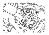
Put matching marks on propeller shaft flange yoke and final drive companion flange.
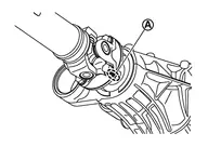
Remove propeller shaft assembly fixing bolts and nuts, and separate propeller shaft assembly from transfer companion flange and final drive companion flange.
Remove propeller shaft assembly.
Remove heat shield plate.
Perform inspection after removal. Refer to Inspection.
INSTALLATION
Note the following, and install in the reverse order of removal.
For non-reusable parts, refer to Exploded View.
For each tightening torque, refer to Exploded View.
Align matching marks
to install propeller shaft flange yoke and final drive companion flange.Align matching marks
to install propeller shaft flange yoke and transfer companion flange.If propeller shaft or final drive has been replaced, connect them as follows:
Install propeller shaft
while aligning matching mark of propeller shaft with matching mark  of final drive on the joint as close as possible.
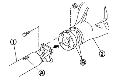
Perform inspection after installation. Refer to Inspection.
Disassembly and Assembly
DISASSEMBLY
Put a matching mark between propeller shaft and flange yoke and remove snap rings .
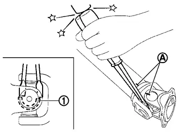
Lightly tap bottom of yoke using a copper hammer and remove journal bearing.
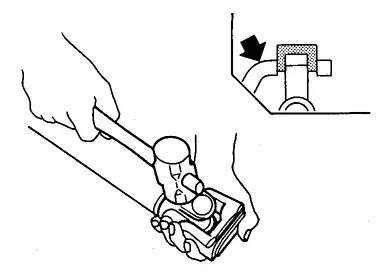
ASSEMBLY
Install journal bearing to journal.
Install bearing
using a vise.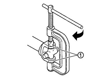
Install journal to propeller shaft so that grease nipple
on journal portion is in the same direction.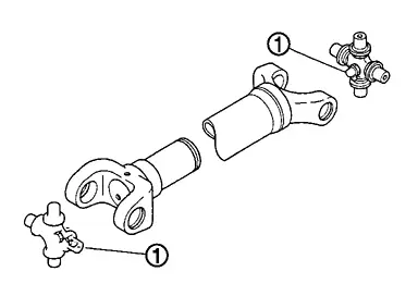
Measure journal axial play. If necessary, select the appropriate snap ring.While pushing to 98 N·m, check the clearance between snap ring and flange yoke .

| Journal axial play | : Refer to Journal. |
Install selected snap ring as shown in the figure.
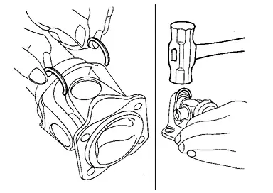
Check that the journal moves smoothly and is below the joint flex torque specification.
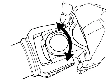
| Joint flex torque | : Refer to Journal. |
Check the journal axial play. Refer to Inspection.
Inspection
INSPECTION AFTER REMOVAL
Appearance
Check propeller shaft tube surface for dents or cracks. If malfunction is detected, replace propeller shaft assembly.
Propeller Shaft Runout
Check propeller shaft runout at several points with a dial indicator. If runout exceeds specifications, replace propeller shaft assembly.

| Propeller shaft runout | : Refer to Propeller Shaft Tube. |
Propeller shaft runout measuring point (Point “
 ”).
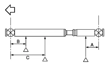
: Front side Dimension A : 80 – 100 mm (3.15 – 3.94 in) B : 100 – 120 mm (3.94 – 4.72 in) C : 268.5 mm (10.57 in)
Journal Axial Play
As shown in the figure, while fixing yoke on one side, check axial play of joint. If the journal axial play exceeds the specification, repair or replace the journal parts.
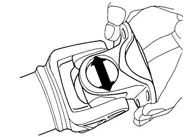
| Journal axial play | : Refer to Journal. |
Joint Flex Torque
Check that the journal moves smoothly and is below the joint flex torque specification. If the joint flex torque exceeds the specification, repair or replace the journal parts.
| Joint flex torque | : Refer to Journal. |
INSPECTION AFTER INSTALLATION
After assembly, perform a driving test to check propeller shaft vibration. If vibration occurred, separate propeller shaft from final drive. Reinstall companion flange by changing the phase between companion flange and propeller shaft by the one bolt hole at a time. Then perform driving test and check propeller shaft vibration again at each point.