Road Wheel
Rotation
Follow the maintenance schedule for tire rotation service intervals. Refer to General Maintenance.

When installing the wheel, tighten wheel nuts to the specified torque. Refer to ROAD WHEEL TIRE : Exploded View.
Perform the ID registration, after tire rotation. Refer to Work Procedure.
Adjustment
BALANCING WHEELS (BONDING WEIGHT TYPE)
Preparation Before Adjustment
Using releasing agent, remove double-faced adhesive tape from the road wheel.
Wheel Balance Adjustment
If a tire balance machine has adhesion balance weight mode settings and drive-in weight mode setting, select and adjust a drive-in weight mode suitable for road wheels.
The details of the adjustment procedure are different for each model of wheel balancer. Therefore, refer to each instruction manual.
Set road wheel on tire balance machine using the center hole as a guide. Start the tire balance machine.
Indicated unbalance value × 5/3 = balance weight to be installed
Calculation example:
23 g (0.81 oz) × 5/3 = 38.33 g (1.35 oz) ⇒ 37.5 g (1.32 oz) balance weight (closer to calculated balance weight value)
Example:
36.2 ⇒ 35 g (1.23 oz)
36.3 ⇒ 37.5 g (1.32 oz)
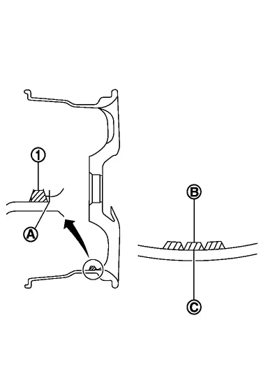
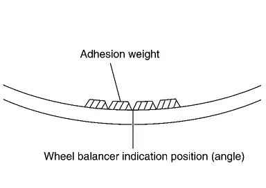
Installed balance weight in the position.When installing balance weight
 to road wheels, set it into the grooved area
 on the inner wall of the road wheel as shown in the figure so that the balance weight center
 is aligned with the tire balance machine indication position (angle)
 .
Start the tire balance machine again.
Install drive-in balance weight on inner side of road wheel in the tire balance machine indication position (angle).
Start the tire balance machine. Check that the inner and outer residual unbalance value is within the allowable unbalance value.
| Allowable unbalance value | |
| Dynamic (At flange) | : Refer to ROAD WHEEL : Service Data. |
| Static (At flange) | :Refer to ROAD WHEEL : Service Data. |