A/C unit assembly
Exploded View (Automatic Air Conditioning)
REMOVAL
LHD models (4WD)
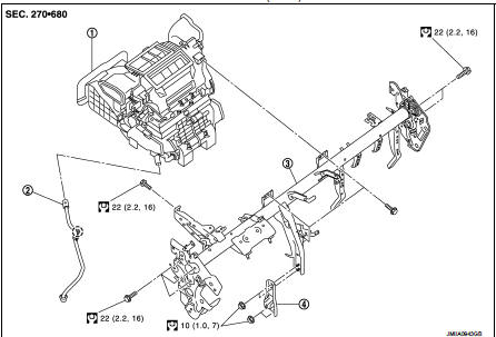
1. A/C unit assembly 2. Drain hose
3. Steering member
4. Instrument stay
 : Clip
 : N·m (kg-m, ft-lb)
DISASSEMBLY
LHD models (4WD)

1. Ventilator seal
2. Defroster seal
3. Upper attachment case 4. Sub defroster door
5. Center ventilator and defroster door 6. Side ventilator seal LH 7. Lower attachment case 8. Side ventilator seal RH 9. Sub harness
10. Power transistor
11. Upper intake case
12. Intake door
13. Lower intake case
14. Blower case LH
15. Blower case RH
16. Blower motor
17. Intake seal
18. A/C unit case RH
19. Air conditioner filter 20. Filter cover
21. Case packing
22. Intake sensor
23. Evaporator
24. Plate
25. Expansion valve grommet 26. O-ring
27. Expansion valve
28. Evaporator cover
29. Heater hose
30. Clamp
31. Heater pipe grommet 32. Heater pipe support 33. Heater core
34. A/C unit case LH
35. Aspirator duct
36. Aspirator
37. Foot door
38. Foot door rod
39. Side ventilator door 40. Air mix door guide
41. Upper air mix door
42. Lower air mix door
A. To water outlet
 : Do not reuse
 : N·m (kg-m, in-lb)
REMOVAL
RHD models (4WD)
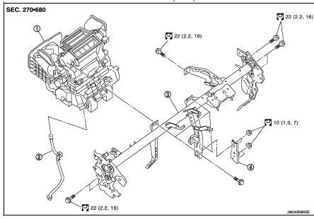
1. A/C unit assembly 2. Drain hose
3. Steering member
4. Instrument stay
 : Clip
 : N·m (kg-m, ft-lb)
DISASSEMBLY
RHD models (4WD)
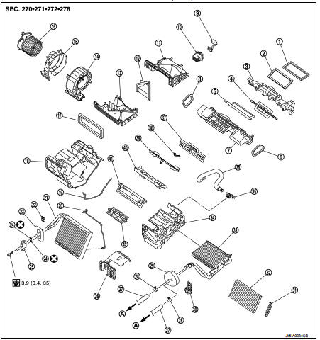
1. Ventilator seal
2. Defroster seal
3. Upper attachment case 4. Sub defroster door
5. Center ventilator and defroster door 6. Side ventilator seal LH 7. Lower attachment case 8. Side ventilator seal RH 9. Sub harness
10. Power transistor
11. Upper intake case
12. Intake door
13. Lower intake case
14. Blower case LH
15. Blower case RH
16. Blower motor
17. Intake seal
18. A/C unit case RH
19. Case packing
20. Intake sensor
21. Evaporator
22. Plate
23. Expansion valve grommet 24. O-ring
25. Expansion valve
26. Evaporator cover
27. Heater hose
28. Clamp
29. Heater pipe grommet 30. Heater pipe support
31. Filter cover
32. Air conditioner filter 33. Heater core
34. A/C unit case LH
35. Aspirator
36. Aspirator duct
37. Foot door
38. Foot door rod
39. Side ventilator door 40. Air mix door guide
41. Upper air mix door
42. Lower air mix door
A. To water outlet
 : Do not reuse
 : N·m (kg-m, in-lb)
REMOVAL
LHD models (2WD)
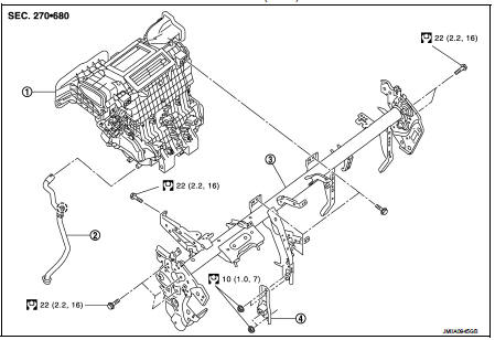
1. A/C unit assembly 2. Drain hose
3. Steering member
4. Instrument stay
 : Clip
 : N·m (kg-m, ft-lb)
DISASSEMBLY
LHD models (2WD)

1. Ventilator seal
2. Defroster seal
3. Upper attachment case 4. Center ventilator door 5. Defroster door
6. Side ventilator seal LH 7. Lower attachment case 8. Side ventilator seal RH 9. Upper intake case
10. Intake door
11. Lower intake case
12. Blower case LH
13. Blower case RH
14. Blower motor
15. Blower motor cover
16. Intake seal
17. A/C unit case RH
18. Air conditioner filter 19. Filter cover
20. Case packing
21. Evaporator cover
22. Intake sensor
23. Evaporator
24. O-ring
25. Expansion valve grommet 26. Expansion valve
27. Fan control amp.
28. Heater pipe support 29. Clamp
30. Heater hose
31. Heater pipe grommet 32. Heater core side packing 33. Heater core
34. A/C unit case LH
35. Aspirator duct
36. Aspirator
37. Side ventilator door 38. Foot door
39. Center lib case
40. Max. cool door
41. Upper air mix door
42. Lower air mix door
A. To water outlet
 : Do not reuse
 : N·m (kg-m, in-lb)
REMOVAL
RHD models (2WD)
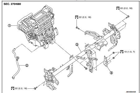
1. A/C unit assembly 2. Drain hose
3. Steering member
4. Instrument stay
 : Clip
 : N·m (kg-m, ft-lb)
DISASSEMBLY
RHD models (2WD)
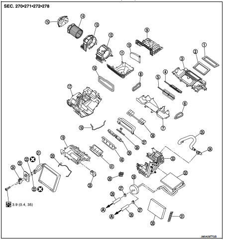
1. Ventilator seal
2. Defroster seal
3. Upper attachment case 4. Center ventilator door 5. Defroster door
6. Side ventilator seal LH 7. Lower attachment case 8. Side ventilator seal RH 9. Upper intake case
10. Intake door
11. Lower intake case
12. Blower case LH
13. Blower case RH
14. Blower motor
15. Blower motor cover
16. Intake seal
17. A/C unit case RH
18. Case packing
19. Evaporator cover
20. Intake sensor
21. Evaporator
22. O-ring
23. Expansion valve grommet 24. Expansion valve
25. Fan control amp.
26. Heater pipe support 27. Clamp
28. Heater hose
29. Heater pipe grommet 30. Air conditioner filter 31. Filter cover
32. Heater core
33. A/C unit case LH
34. Aspirator
35. Aspirator duct
36. Side ventilator door 37. Foot door
38. Center lib case
39. Max. cool door
40. Upper air mix door
41. Lower air mix door
A. To water outlet
 : Do not reuse
 : N·m (kg-m, in-lb)
Exploded View (Manual Air Conditioning)
REMOVAL
LHD models (4WD)
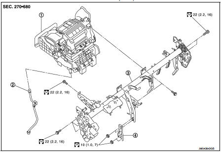
1. A/C unit assembly 2. Drain hose
3. Steering member
4. Instrument stay
 : Clip
 : N·m (kg-m, ft-lb)
DISASSEMBLY
LHD models (4WD)
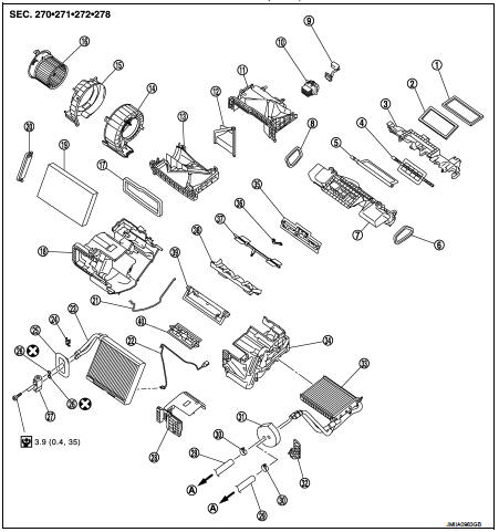
1. Ventilator seal
2. Defroster seal
3. Upper attachment case 4. Center ventilator door 5. Defroster door
6. Side ventilator seal LH 7. Lower attachment case 8. Side ventilator seal RH 9. Sub harness
10. Blower fan resistor 11. Upper Intake case
12. Intake door
13. Lower intake case
14. Blower case LH
15. Blower case RH
16. Blower motor
17. Intake seal
18. A/C unit case RH
19. Air conditioner filter 20. Filter cover
21. Case packing
22. Thermo control amp. 23. Evaporator
24. Plate
25. Expansion valve grommet 26. O-ring
27. Expansion valve
28. Evaporator cover
29. Heater hose
30. Clamp
31. Heater pipe grommet 32. Heater pipe support 33. Heater core
34. A/C unit case LH
35. Foot door
36. Foot door rod
37. Side ventilator door 38. Air mix door guide
39. Upper air mix door
40. Lower air mix door
A. To water outlet
 : Do not reuse
 : N·m (kg-m, in-lb)
REMOVAL
RHD models (4WD)
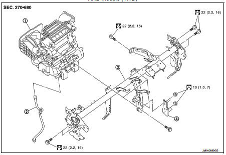
1. A/C unit assembly 2. Drain hose
3. Steering member
4. Instrument stay
 : Clip
 : N·m (kg-m, ft-lb)
DISASSEMBLY
RHD models (4WD)

1. Ventilator seal
2. Defroster seal
3. Upper attachment case 4. Center ventilator door 5. Defroster door
6. Side ventilator seal LH 7. Lower attachment case 8. Side ventilator seal RH 9. Sub harness
10. Blower fan resistor 11. Upper intake case
12. Intake door
13. Sub intake door
14. Lower Intake case
15. Blower case LH
16. Blower case RH
17. Blower motor
18. Intake seal
19. A/C unit case RH
20. Case packing
21. Thermo control amp.
22. Evaporator
23. Plate
24. Expansion valve grommet 25. O-ring
26. Expansion valve
27. Evaporator cover
28. Heater hose
29. Clamp
30. Heater pipe grommet
31. Heater pipe support 32. Filter cover
33. Air conditioner filter 34. Heater core
35. A/C unit case LH
36. Foot door
37. Foot door rod
38. Side ventilator door 39. Air mix door guide
40. Upper air mix door
41. Lower air mix door
A. To water outlet
 : Do not reuse
 : N·m (kg-m, in-lb)
REMOVAL
LHD models (2WD)

1. A/C unit assembly 2. Drain hose
3. Steering member
4. Instrument stay
 : Clip
 : N·m (kg-m, ft-lb)
DISASSEMBLY
LHD models (2WD)
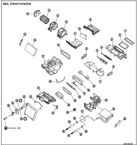
1. Ventilator seal
2. Defroster seal
3. Upper attachment case 4. Center ventilator door 5. Defroster door
6. Side ventilator seal LH 7. Lower attachment case 8. Side ventilator seal RH 9. Upper intake case
10. Intake door
11. Lower intake case
12. Blower case LH
13. Blower case RH
14. Blower motor
15. Blower motor cover
16. Intake seal
17. A/C unit case RH
18. Air conditioner filter 19. Filter cover
20. Case packing
21. Evaporator cover
22. Thermo control amp. 23. Evaporator
24. O-ring
25. Expansion valve grommet 26. Expansion valve
27. Blower fan resistor
28. Heater pipe support 29. Clamp
30. Heater hose
31. Heater pipe grommet 32. Heater core side packing 33. Heater core
34. A/C unit case LH
35. Side ventilator door 36. Foot door
37. Center lib case
38. Max. cool door
39. Upper air mix door
40. Lower air mix door
A. To water outlet
 : Do not reuse
 : N·m (kg-m, in-lb)
REMOVAL
RHD models (2WD)
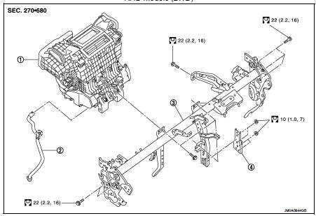
1. A/C unit assembly 2. Drain hose
3. Steering member
4. Instrument stay
 : Clip
 : N·m (kg-m, ft-lb)
DISASSEMBLY
RHD models (2WD)
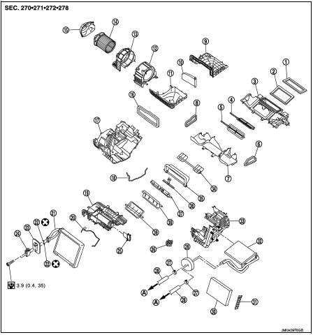
1. Ventilator seal
2. Defroster seal
3. Upper attachment case 4. Center ventilator door 5. Defroster door
6. Side ventilator seal LH 7. Lower attachment case 8. Side ventilator seal RH 9. Upper intake case
10. Intake door
11. Lower intake case
12. Blower case LH
13. Blower case RH
14. Blower motor
15. Blower motor cover
16. Intake seal
17. A/C unit case RH
18. Case packing
19. Evaporator cover
20. Thermo control amp. 21. Evaporator
22. O-ring
23. Expansion valve grommet 24. Expansion valve
25. Blower fan resistor 26. Heater pipe support 27. Clamp
28. Heater hose
29. Heater pipe grommet 30. Air conditioner filter 31. Filter cover
32. Heater core
33. A/C unit case LH
34. Ventilator door side 35. Foot door
36. Center lib case
37. Max. cool door
38. Upper air mix door
39. Lower air mix door
A. To water outlet
 : Do not reuse
 : N·m (kg-m, in-lb)
A/C unit assembly : Removal and Installation
CAUTION:Perform lubricant return operation before each refrigeration system disassembly. However, if a large amount of refrigerant or lubricant is detected, never perform lubricant return operation. Refer to HA- 78, "Perform Lubricant Return Operation".
REMOVAL
1. Use a refrigerant collecting equipment (for HFC-134a) to discharge the refrigerant. Refer to HA-76, "Recycle Refrigerant". 2. Drain engine coolant from cooling system. Refer to CO-11, "Draining".3. Remove cowl top extension. Refer to EXT-20, "Removal and Installation".
4. Remove mounting nut, and then move lower dash insulator aside.
 : Nut
 : Vehicle front

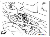
5. Remove mounting bolt (A), and then disconnect low-pressure flexible hose (1) and high-pressure pipe (2) from expansion valve. Refer to HA-116, "EXPANSION VALVE : Removal and Installation".
CAUTION:Cap or wrap the joint of the A/C piping and expansion valve with suitable material such as vinyl tape to avoid the entry of air.
 : Vehicle front
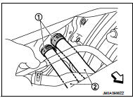
6. Remove clamps (1), and then disconnect heater hose (2) from A/C unit assembly.
 : Vehicle front
7. Remove instrument panel assembly. Refer to IP-13, "Removal and Installation". 8. Remove side ventirator duct. Refer to VTL-12, "SIDE VENTILATOR DUCT : Removal and Installation".
9. Remove mounting bolts (A) of ground wire LH side and mounting bolt (B) of ground wire RH side.
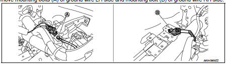
10. Remove rear heater duct 1. Refer to VTL-13, "REAR HEATER DUCT 1 : Removal and Installation". (LHD models only)
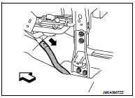
11. Disconnect drain hose (1) from A/C unit assembly.
 : Vehicle front
12. Remove mounting nuts (A), and then remove instrument stay.
 : Vehicle front
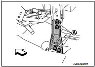
13. Remove J/B fixing screws (A), and then remove J/B.
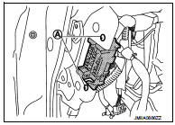
14. Remove BCM fixing screws (A), and then remove BCM.
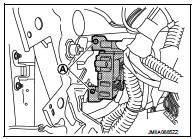
15. Disconnect harness connectors and clips required to remove the steering member, and then move the vehicle harness to the position without hindrance for work.
16. Move steering column assembly to a position where it dose not inhibit work. Refer to ST-10, "Removal and Installation"
17. Remove mounting bolts (A) and (B), and then remove steering member (1) from vehicle.

18. Remove A/C unit assembly from vehicle.
INSTALLATION
Note the following items, and then install in the reverse order of removal.
CAUTION:• Replace O-rings with new ones. Then apply compressor oil to them when installing.
• Check for leakages when recharging refrigerant. Refer to HA-74, "Leak Test".
NOTE:Refer to CO-12, "Refilling" when filling radiator with engine coolant.
Evaporator : Removal and Installation
REMOVAL
1. Remove A/C unit assembly. Refer to HA-113, "A/C UNIT ASSEMBLY : Removal and Installation". 2. Disassemble A/C unit assembly, and then remove evaporator.3. Remove intake sensor from evaporator. (automatic air conditioning) 4. Remove thermo control amp. from evaporator. (manual air conditioning) 5. Remove mounting bolts, and then remove expansion valve.
INSTALLATION
Note the following items, and then install in the reverse order of removal.
CAUTION:• Replace O-rings with new ones. Then apply compressor oil to them when installing. • When install the intake sensor (automatic air conditioning) or the thermo control amp. (manual air conditioning), set the same position before replacement. • Never rotate the bracket insertion part when removing and installing the intake sensor (automatic air conditioning) or the thermo control amp. (manual air conditioning).
• Perform lubricant adjusting procedure after installing new evaporator. Refer to HA-78, "Lubricant Adjusting Procedure for Components Replacement Except Compressor".
Heater core : Removal and Installation
REMOVAL
1. Remove A/C unit assembly. Refer to HA-113, "A/C UNIT ASSEMBLY : Removal and Installation". 2. Remove heater pipe grommet and heater pipe support from A/C unit assembly. 3. Remove foot duct LH. Refer to VTL-14, "FOOT DUCT : Removal and Installation".4. Remove heater core side packing. (for 2WD LHD and AWD LHD models only) 5. Slide heater core to leftward, and then remove heater core from A/C unit assembly.
INSTALLATION
Install in the reverse order of removal.
Expansion valve : Removal and Installation
CAUTION:Perform lubricant return operation before each refrigeration system disassembly. However, if a large amount of refrigerant or lubricant is detected, never perform lubricant return operation. Refer to HA- 78, "Perform Lubricant Return Operation".
REMOVAL
1. Use a refrigerant collecting equipment (for HFC-134a) to discharge the refrigerant. Refer to HA-76, "Recycle Refrigerant". 2. Remove cowl top extension. Refer to EXT-20, "Removal and Installation".3. Remove mounting nut, and then move lower dash insulator aside.
 : Nut
 : Vehicle front
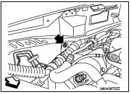
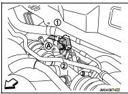
4. Remove mounting bolt (A), and then disconnect low-pressure flexible hose (1) and high-pressure pipe (2) from expansion valve. Refer to HA-116, "EXPANSION VALVE : Removal and Installation".
CAUTION:Cap or wrap the joint of the A/C piping and expansion valve with suitable material such as vinyl tape to avoid the entry of air.
 : Vehicle front
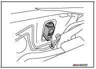
5. Remove mounting bolts (A), and then remove expansion valve from evaporator.
INSTALLATION
Note the following items, and then install in the reverse order of removal.
CAUTION:• Replace O-rings with new ones. Then apply compressor oil to them when installing.
• Check for leakages when recharging refrigerant. Refer to HA-74, "Leak Test".