Body Repair

Body construction

In this manual: Body Repair
Foreword — 1General information — 45Engine Mechanical MR16DDT — 61Engine Mechanical HR16DE — 52Engine Mechanical K9K — 46Engine Lubrication System MR16DDT — 18Engine Lubrication System HR16DE — 14Engine Lubrication System K9K — 11Engine Cooling System MR16DDT — 28Engine Cooling System HR16DE — 29Engine Cooling System K9K — 24Engine Control System MR16DDT — 163Engine Control System HR16DE — 115Engine Control System K9K — 129Fuel System MR16DDT — 13Fuel system HR16DE — 11Fuel system K9K — 12Exhaust system MR16DDT — 7Exhaust system HR16DE — 10Exhaust system K9K — 7Starting system — 24Accelerator control system — 6Clutch — 25Driveline transfer: TY21B — 77Driveline rear propeller Shaft: 3Fφ16-ETJ75 — 12Driveline rear final drive: RTVS — 31Transaxle & transmission 5MT: RS5F92R — 31Transaxle & transmission 6MT: RS6F94R — 30Transaxle & transmission CVT: RE0F10B — 93Transaxle & transmissioN CVT: RE0F11A — 103Front Axle MR16DDT — 18Front Axle HR16DE — 17Front Axle K9K — 17Rear Axle 2WD — 6Rear Axle 4WD — 13Front Suspension — 21Rear Suspension 2WD — 13Rear Suspension 4WD — 17Road Wheels & Tires — 6Brake System LHD — 24Brake System RHD — 24Parking Brake System — 8Brake Control System without ESP — 44Brake Control System with ESP — 63Steering System — 14Steering Control System — 27Seat Belt — 8SRS Airbag — 24SRS Airbag Control System — 93Ventilation System — 11Heater & Air Conditioning System HR16DE — 28Heater & Air Conditioning System MR16DDT — 28Heater & Air Conditioning Control System Type 1 — 49Heater & Air Conditioning Control System Type 2 — 51Heater & Air Conditioning Control System Type 3 — 32Heater & Air Conditioning Control System Type 4 — 40Heater & Air Conditioning Control System Type 5 — 21Interior — 16Instrument Panel — 10Seat — 18Door & Lock Type 1 — 83Door & Lock type 2 — 80Door & Lock type 3 — 65Door & Lock type 4 — 60Security Control System with intelligent key system — 82Security Control System without intelligent key system — 41Glass & Window System — 15Power Window Control System — 28Body Repair — 13Exterior — 20Mirrors — 26Exterior Lighting System Halogen type — 51Interior Lighting System — 24Wiper & Washer — 45Defogger — 31Horn — 4Power Outlet — 4Body Control System With intelligent key system — 21Body Control System Without intelligent key system — 23LAN system can fundamental — 6LAN system can — 31LAN System can system (type 1) — 1LAN System can system (type 2) — 1LAN System can system (type 3) — 1LAN System can system (type 4) — 1LAN System can system (type 5) — 1LAN System can system (type 6) — 1LAN System can system (type 7) — 2LAN System can system (type 8) — 1LAN System can system (type 9) — 1LAN System can system (type 10) — 1LAN System can system (type 11) — 1Power Control System IPDM E/R (with I-key) — 14Power Control System IPDM E/R (without I-key) — 14Power Control System Power distribution system — 25Charging System — 22Power Supply, Ground & Circuit Elements — 20Meter, Warning Lamp & Indicator — 33Warning Chime System — 22Audio, Visual & Navigation System Audio without navigation — 30Audio, Visual & Navigation System Audio with navigation — 33Audio, Visual & Navigation System NISSAN dynamic control system — 22Cruise Control System — 1Drive Mode System — 10Maintenance — 14
~3min read

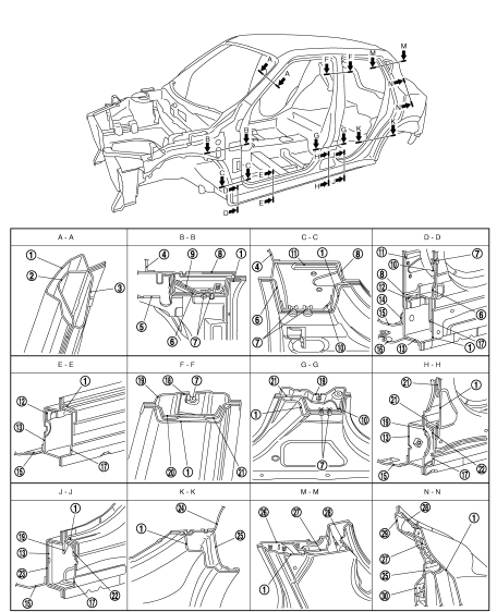
Body Construction (RHD Models)

1. Outer side body

1. Outer side body
2. Outer front pillar reinforcement 3. Upper inner front pillar 4. Lower dash
5. Hoodledge reinforcement 6. Lower front pillar hinge brace 7. Weld nut
8. Side dash
9. Upper hinge plate
10. Lower hinge plate
11. Inner front pillar reinforcement 12. Inner front sill reinforcement 13. Inner sill
14. Front floor reinforcement 15. Front floor
16. Front outrigger
17. Outer sill reinforcement 18. Plate nut
19. Inner center pillar 20. Center pillar reinforcement 21. Center pillar hinge brace 22. Center sill reinforcement 23. Inner sill extension 24. Inner rear wheelhouse 25. Outer rear wheelhouse 26. Rear roof rail brace 27. Inner rear pillar reinforcement 28. Rear fender extension 29. Inner rear pillar
30. Inner rear wheelhouse reinforcement

Body Construction (LHD Models)
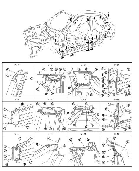
1. Outer side body

1. Outer side body
2. Outer front pillar reinforcement 3. Upper inner front pillar 4. Lower dash
5. Hoodledge reinforcement 6. Lower front pillar hinge brace 7. Weld nut
8. Side dash
9. Upper hinge plate
10. Lower hinge plate
11. Inner front pillar reinforcement 12. Inner front sill reinforcement 13. Inner sill
14. Front floor reinforcement 15. Front floor
16. Front outrigger
17. Outer sill reinforcement 18. Plate nut
19. Inner center pillar 20. Center pillar reinforcement 21. Center pillar hinge brace 22. Center sill reinforcement 23. Inner sill extension 24. Inner rear wheelhouse 25. Outer rear wheelhouse 26. Rear roof rail brace 27. Inner rear pillar reinforcement 28. Rear fender extension 29. Inner rear pillar
30. Inner rear wheelhouse reinforcement 31. Upper inner front pillar reinforcement

Rear Fender Hemming Process

1. A wheel arch is to be installed and hemmed over the left and right outer wheel houses.

2. In order to hem the wheel arch, it is necessary to repair any damaged or defaced parts around outer wheel house.

CAUTION:
Ensure that the area that is to be glued around the outer wheelhouse is undamaged or defaced.

PROCEDURE OF THE HEMMING PROCESS

• Peel off old bonding material on the surface of the outer wheelhouse and clean thoroughly. • Peel off a primer coat in the specified area where new adhesive is to be applied on rear fender (the replacing part).

• Apply new adhesive to both specified areas of the outer wheelhouse and rear fender.

<Adhesive> 3M™ Automix™ Panel Bonding Adhesive 08115 or equivalent

• Attach rear fender to the body of the car, and weld the required part except the hemming part.
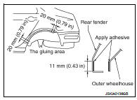
• Bend the welded part starting from the center of the wheel arch

• Bend the welded part starting from the center of the wheel arch gradually with a hammer and a dolly. (Also hem the end of the flange.)
• Hemming with a hammer is conducted to an approximate angle of 80 degrees.

• Starting from the center, hem the wheel arch gradually, using slight

• Starting from the center, hem the wheel arch gradually, using slight back and forth motion with a hemming tool.

• Seal up the area around the hemmed end of the flange.

• Seal up the area around the hemmed end of the flange.

Replacement operations