Brake fluid
Inspection
BRAKE FLUID LEVEL
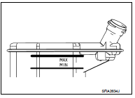
• Check that the fluid level in the reservoir tank is within the specified range (MAX – MIN lines). • Visually check for any brake fluid leakage around the reservoir tank. • Check the brake system for any leakage if the fluid level is extremely low (lower than MIN). • Check the brake system for fluid leakage if the warning lamp remains illuminated even after the parking brake is released.• Check the reservoir tank for the mixing of foreign matter (e.g. dust) and oils other than brake fluid.
BRAKE LINE
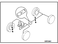
1. Check brake line (tubes and hoses) for cracks, deterioration or other damage. Replace any damaged parts.2. Depress the brake pedal with a force of 785 N (80 kg, 176 lb) and hold down the pedal for approximately 5 seconds with the engine running. Check for any fluid leakage.
CAUTION:Retighten the applicable connection to the specified torque and repair any abnormal (damaged, worn or deformed) part if any brake fluid leakage is present.
Draining
CAUTION:• Never spill or splash brake fluid on painted surfaces. Brake fluid may seriously damage paint. Wipe it off immediately and wash with water if it gets on a painted surface. For brake component parts, never wash them with water.
• Turn the ignition switch OFF and disconnect the ABS actuator and electric unit (control unit) harness connector or the battery negative terminal before performing work.
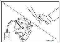
1. Connect a vinyl tube to the bleed valve.2. Depress the brake pedal and loosen the bleeder valve to gradually discharge brake fluid.
Refilling
CAUTION:• Turn the ignition switch OFF and disconnect the ABS actuator and electric unit (control unit) harness connector or the battery negative terminal before performing work.
• Never spill or splash brake fluid on painted surfaces. Brake fluid may seriously damage paint. Wipe it off immediately and wash with water if it gets on a painted surface. For brake component parts, never wash them with water.
1. Check that there is no foreign material in the reservoir tank, and refill with new brake fluid.
CAUTION:• Never reuse drained brake fluid.
• Never allow foreign matter (e.g. dust) and oils other than brake fluid to enter the reservoir tank.
2. Loosen the bleeder valve, slowly depress the brake pedal to the full stroke, and then release the pedal.
Repeat this operation at intervals of 2 or 3 seconds until new brake fluid is discharged. Then close the bleeder valve with the brake pedal depressed. Repeat the same work on each wheel.3. Perform the air bleeding. Refer to BR-81, "Bleeding Brake System".
Bleeding Brake System
CAUTION:• Turn the ignition switch OFF and disconnect the ABS actuator and electric unit (control unit) harness connector or the battery negative terminal before performing the work.
• Monitor the fluid level in the reservoir tank while performing the air bleeding
• Never spill or splash brake fluid on painted surfaces. Brake fluid may seriously damage paint. Wipe it off immediately and wash with water if it gets on a painted surface. For brake component parts, never wash them with water.
1. Check that there is no foreign material in the reservoir tank, and refill with new brake fluid.
CAUTION:• Never reuse drained brake fluid.
• Never allow oils other than brake fluid to enter the reservoir tank.
2. Connect a vinyl tube to the bleeder valve of the rear left brake. 3. Fully depress the brake pedal 4 to 5 times. 4. Loosen the bleeder valve and bleed air with the brake pedal depressed, and then quickly tighten the bleeder valve. 5. Repeat steps 3 and 4 until all of the air is out of the brake line.6. Tighten the bleeder valve to the specified torque.
• Front disc brake: refer to BR-122, "BRAKE CALIPER ASSEMBLY : Exploded View".• Rear disc brake: refer to BR-130, "BRAKE CALIPER ASSEMBLY : Exploded View".
7. Perform steps 2 to 6. Occasionally fill with the brake fluid in order to keep it in the reservoir tank at least half of MAX line. Bleed air in the following order: rear left brake → front right brake → rear right brake → and front left brake in order. 8. Check that the fluid level in the reservoir tank is within the specified range after air bleeding. Refer to BR- 80, "Inspection".9. Check each item of brake pedal. Adjust it if the measurement value is not the standard. Refer to BR-77, "Inspection and Adjustment".