Clutch pedal
INSPECTION
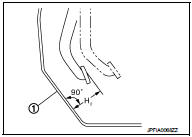
The Height of Clutch Pedal 1. Turn the floor carpet.2. Check that the clutch pedal height “H1” from the dash lower panel (1) is within the reference value.
Clutch pedal height “H1” : Refer to CL-35, "Clutch Pedal".
3. Replace clutch pedal if the height is outside the reference value.

Clutch Pedal Height When Disengaging The Clutch 1. Securely engage the parking brake. 2. Turn the floor carpet.
3. Start the engine and run at idle.
4. Fully depress clutch pedal and shift to the 1st gear.
CAUTION:Securely depress the brake pedal with shifter lever in 1st gear.
5. Gradually release the clutch pedal and check that the clutch pedal height “H2” from the dash lower panel (1) is within the reference value with a scale immediately before the clutch is engaged.
Clutch pedal height at clutch disengagement “H2” : Refer to CL-35, "Clutch Pedal".
NOTE:
Although the clutch pedal height differs according to whether the clutch gets disengaged or engaged, clutch-engaged case is regarded as clutch-disengaged case for easier inspection.
6. Replace clutch pedal if the height is outside the reference value.
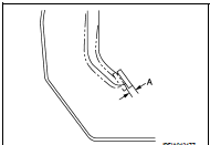
Clutch Pedal Play
1. Push the pedal pad by hand until a resistance can be felt and check that the play “A” on the upper surface of the pedal pad is within the reference value.
Clutch pedal play “A” : Refer to CL-35, "Clutch Pedal".
2. Replace clutch pedal if the play is outside the reference value.
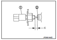
Position of Clutch Interlock Switch (With Push-Button Ignition Switch System)
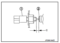
• LHD
- Check that the clearance “C” between the thread end of clutch interlock switch (1) and stopper rubber (2) is within the specified value while clutch pedal is fully depressed.
Clearance “C” : Refer to CL-35, "Clutch Pedal".
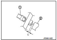
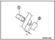
• RHD
- Check that the clearance “C” between the thread end of clutch interlock switch (1) and clutch pedal (2) is within the specified value while clutch pedal is fully depressed.
Clearance “C” : Refer to CL-35, "Clutch Pedal".
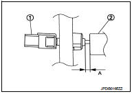
Position of Clutch Pedal Position Switch (With ASCD or With Push-Button Ignition Switch System) Check that the clearance “A” between the thread end of clutch pedal position switch (1) and clutch pedal (2) is within the specified value while clutch pedal is fully released.
Clearance “A” : Refer to CL-35, "Clutch Pedal".
ADJUSTMENT
Position of Clutch Interlock Switch (With Push-Button Ignition Switch System) 1. Disconnect the clutch interlock switch connector. 2. Loosen the clutch interlock switch 45 degrees counterclockwise. 3. With the clutch pedal fully depressed, press into the clutch interlock switch (1) until it reaches the stopper rubber (2) and turn the switch clockwise by 45 degrees to secure it. (For LHD) CAUTION:The clearance “C” show in the figure must be within the specified value.
Clearance “C” : Refer to CL-35, "Clutch Pedal".
NOTE:
Fully depressed clutch pedal means a clutch pedal condition that the clutch pedal lever contacts the pedal stopper rubber.
4. With the clutch pedal fully depressed, press into the clutch interlock switch (1) until it reaches the clutch pedal (2) and turn the switch clockwise by 45 degrees to secure it. (For RHD) CAUTION:
The clearance “C” show in the figure must be within the specified value
.
Clearance “C” : Refer to CL-35, "Clutch Pedal".
NOTE:
Fully depressed clutch pedal means a clutch pedal condition that the clutch pedal lever contacts the pedal stopper rubber.
Position of Clutch Pedal Position Switch (With ASCD or With Push-Button Ignition Switch System)
1. Disconnect the clutch pedal position switch connector. 2. Loosen the clutch pedal position switch 45 degrees counterclockwise.
3. Press-fit the clutch pedal position switch (1) until the clutch pedal position switch hits the clutch pedal (2) 45 degrees clockwise while pulling the pedal pad slightly.
CAUTION:The clearance “A” show in the figure must be within the specified value.
Clearance “A” : Refer to CL-35, "Clutch Pedal".
