Brake Control System without ESP

Component parts

In this manual: Brake Control System without ESP
Foreword — 1General information — 45Engine Mechanical MR16DDT — 61Engine Mechanical HR16DE — 52Engine Mechanical K9K — 46Engine Lubrication System MR16DDT — 18Engine Lubrication System HR16DE — 14Engine Lubrication System K9K — 11Engine Cooling System MR16DDT — 28Engine Cooling System HR16DE — 29Engine Cooling System K9K — 24Engine Control System MR16DDT — 163Engine Control System HR16DE — 115Engine Control System K9K — 129Fuel System MR16DDT — 13Fuel system HR16DE — 11Fuel system K9K — 12Exhaust system MR16DDT — 7Exhaust system HR16DE — 10Exhaust system K9K — 7Starting system — 24Accelerator control system — 6Clutch — 25Driveline transfer: TY21B — 77Driveline rear propeller Shaft: 3Fφ16-ETJ75 — 12Driveline rear final drive: RTVS — 31Transaxle & transmission 5MT: RS5F92R — 31Transaxle & transmission 6MT: RS6F94R — 30Transaxle & transmission CVT: RE0F10B — 93Transaxle & transmissioN CVT: RE0F11A — 103Front Axle MR16DDT — 18Front Axle HR16DE — 17Front Axle K9K — 17Rear Axle 2WD — 6Rear Axle 4WD — 13Front Suspension — 21Rear Suspension 2WD — 13Rear Suspension 4WD — 17Road Wheels & Tires — 6Brake System LHD — 24Brake System RHD — 24Parking Brake System — 8Brake Control System without ESP — 44Brake Control System with ESP — 63Steering System — 14Steering Control System — 27Seat Belt — 8SRS Airbag — 24SRS Airbag Control System — 93Ventilation System — 11Heater & Air Conditioning System HR16DE — 28Heater & Air Conditioning System MR16DDT — 28Heater & Air Conditioning Control System Type 1 — 49Heater & Air Conditioning Control System Type 2 — 51Heater & Air Conditioning Control System Type 3 — 32Heater & Air Conditioning Control System Type 4 — 40Heater & Air Conditioning Control System Type 5 — 21Interior — 16Instrument Panel — 10Seat — 18Door & Lock Type 1 — 83Door & Lock type 2 — 80Door & Lock type 3 — 65Door & Lock type 4 — 60Security Control System with intelligent key system — 82Security Control System without intelligent key system — 41Glass & Window System — 15Power Window Control System — 28Body Repair — 13Exterior — 20Mirrors — 26Exterior Lighting System Halogen type — 51Interior Lighting System — 24Wiper & Washer — 45Defogger — 31Horn — 4Power Outlet — 4Body Control System With intelligent key system — 21Body Control System Without intelligent key system — 23LAN system can fundamental — 6LAN system can — 31LAN System can system (type 1) — 1LAN System can system (type 2) — 1LAN System can system (type 3) — 1LAN System can system (type 4) — 1LAN System can system (type 5) — 1LAN System can system (type 6) — 1LAN System can system (type 7) — 2LAN System can system (type 8) — 1LAN System can system (type 9) — 1LAN System can system (type 10) — 1LAN System can system (type 11) — 1Power Control System IPDM E/R (with I-key) — 14Power Control System IPDM E/R (without I-key) — 14Power Control System Power distribution system — 25Charging System — 22Power Supply, Ground & Circuit Elements — 20Meter, Warning Lamp & Indicator — 33Warning Chime System — 22Audio, Visual & Navigation System Audio without navigation — 30Audio, Visual & Navigation System Audio with navigation — 33Audio, Visual & Navigation System NISSAN dynamic control system — 22Cruise Control System — 1Drive Mode System — 10Maintenance — 14
~3min read

Component Parts Location

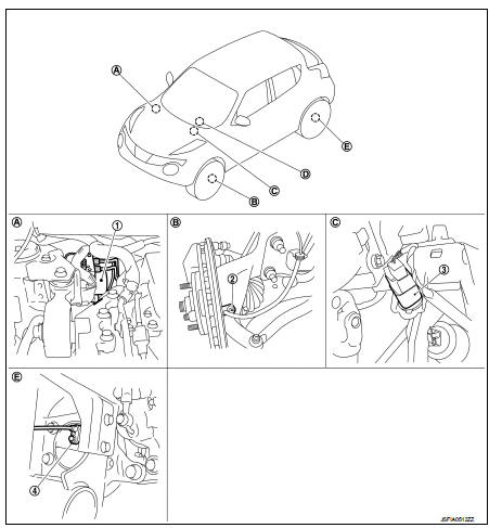
LHD

1. ABS actuator and electric unit (control

1. ABS actuator and electric unit (control unit)
2. Front wheel sensor
3. Stop lamp switch
4. Rear wheel sensor

A. Inside engine room B. Steering knuckle
C. Brake pedal
D. ABS warning lamp, brake warning lamp (in combination meter) E. Rear wheel hub and bearing assembly

RHD
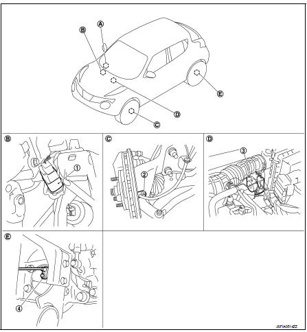
1. Stop lamp switch

1. Stop lamp switch
2. Front wheel sensor
3. ABS actuator and electric unit (control unit)
4. Rear wheel sensor

A. ABS warning lamp, brake warning lamp (in combination meter) B. Brake pedal
C. Steering knuckle
D. Inside engine room
E. Rear wheel hub and bearing assembly

Component Description


Wheel Sensor and Sensor Rotor

Wheel Sensor and Sensor Rotor

NOTE:
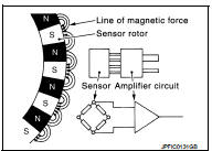
• Wheel sensor of front wheel is installed on steering knuckle. • Sensor rotor of front wheel is integrated in wheel hub and bearing assembly. • Wheel sensor of rear wheel is installed on wheel hub and bearing assembly. • Sensor rotor of rear wheel is integrated in wheel hub and bearing assembly. • Never measure resistance and voltage value using a tester because sensor is active sensor. • Downsize and weight reduction is aimed. IC for detection portion and magnet for sensor rotor are adopted. • Power supply is supplied to detection portion so that magnetic field line is read. Magnetic field that is detected is converted to current signal.

• When sensor rotor rotates, magnetic field changes. Magnetic field change is converted to current signals (rectangular wave) and is transmitted to ABS actuator and electric unit (control unit). Change of magnetic field is proportional to wheel speed.
ABS Actuator and Electric Unit (Control Unit)

ABS Actuator and Electric Unit (Control Unit)

Electric unit (control unit) is integrated with actuator and comprehensively controls ABS function and EBD function.

ELECTRIC UNIT (CONTROL UNIT)

• Brake fluid pressure are controlled according to signals from each sensor.

• If malfunction is detected, the system enters fail-safe mode.

ACTUATOR

The following components are integrated with ABS actuator.

Pump
Returns the brake fluid reserved in reservoir to master cylinder by reducing pressure.

Motor
Activates the pump according to signals from ABS actuator and electric unit (control unit).

Motor Relay
Operates the motor ON/OFF according to signals from ABS actuator and electric unit (control unit).

Actuator Relay (Main Relay) Operates each valve ON/OFF according to signals from ABS actuator and electric unit (control unit).

ABS IN Valve
Switches the fluid pressure line to increase or hold according to signals from control unit.

NOTE

:
Valve is a solenoid valve.

ABS OUT Valve
Switches the fluid pressure line to increase, hold or decrease according to signals from control unit.

NOTE

:
Valve is a solenoid valve.

Inlet Valve
Brake fluid sucked from the reservoir by the pump does not backflow.

NOTE

:
Valve is a check valve.

Outlet Valve
Brake fluid discharged from the pump does not backflow.

NOTE

:
Valve is a check valve.

Return Check Valve
Returns the brake fluid from brake caliper to master cylinder by bypassing orifice of each valve when brake is released.

Reservoir
Temporarily reserves the brake fluid drained from brake caliper, so that pressure efficiently decreases when decreasing pressure of brake caliper.

Stop Lamp Switch

Detects the operation status of brake pedal and transmits converted electric signal to ABS actuator and electric unit (control unit).